
US 7894
UNITED STATES PATENT OFFICE.
JAMES WARNER, OF SPRING FIELD, MASSACHUSETTS.
IMPROVED MEANS FOR REVOLVING THE BREECHES OF REPEATING FREARMS.
Specification forming part of Letters Patent No. 7,894, dated January 7, 1851.
To all whom it may concern:
Be it known that I, James Warner, of Springfield, in the county of Hampden and State of Massachusetts, have invented an Improvement in Revolving Fire-Arms; and I do hereby declare the following to be a full, clear, and exact description of the same, reference being had to the annexed drawings, making a part of this specification, in which—
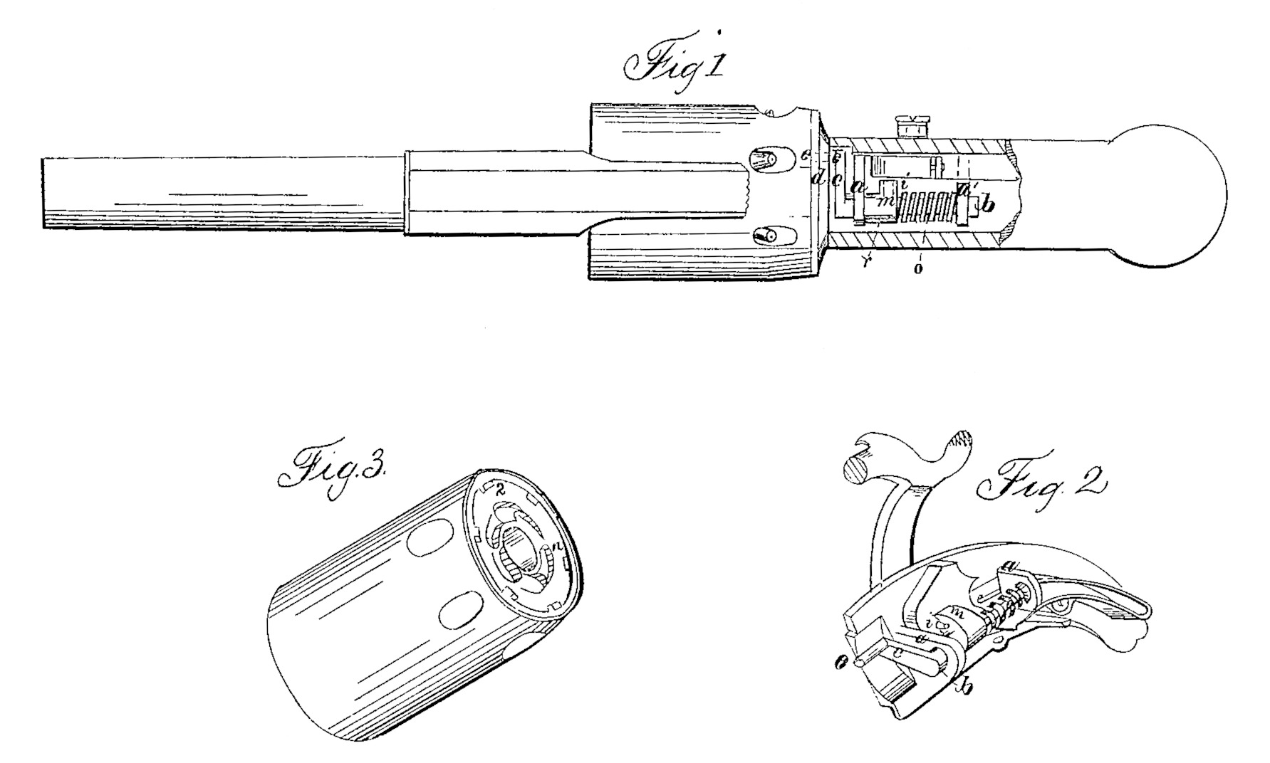
Figure I is a top view of the working parts by which the revolution is effected. Fig. II is a view in perspective of the lock detached from the pistol. Fig. III is a view in perspective of the rear end of the chamber; and similar letters refer to similar parts throughout.
The nature of my invention consists in such construction of a revolving chambered pistol that the chambers will be caused to revolve by the action of a lever of which the fulcrum or axis of vibration is in line, or nearly so, with the axis of rotation of the chamber, whereby I am enabled to effect the revolution of the chambers with greater certainty, and by simplifying the construction to diminish the cost of manufacture, as well as the liability to derangement in rapid action.
The general appearance of my pistol is as of usual construction; but on the plate of the lock, and at right angles with it, extending into the hollow space within the grasp or handle, I affix two arms, a a’, as supports for the shaft and lever which effect the rotation. In these arms a shaft, b, is fitted to have vibratory motion at such distance from the plate of the lock that its axis of vibration will lie in the continuation of the line of rotation of the chambers; or it may beat a short distance farther from the plate, as shown in Fig. I. On the forward end of this shaft is a crank, c, extending nearly to the plate of the lock, and the pin e of this crank is made solid with it and operates through a circular slot in the shield-plated upon a ratchet on the rear end of the chambers, which is of the common construction seen in Fig. III. A pin, i, projects from the forward part of the tumbler, and is for the purpose of imparting motion to the shaft. This it effects by means of a double cam formed on the shaft, as seen at m, and between the forks of which the pin works, as seen in Fig. II. The shaft has a degree of horizontal sliding motion equal to the depth of the notches n, and when thrown forward by the helical spring o pressing against the rear arm a’ a shoulder, r, on the shaft bears against the arm a, keeping it in proper place. The chamber is held in position by a device of common construction which operates in the notch s on the rear end of the chamber.
The operation will be thus: When the hammer rests upon the nipple the pine of the crank will be protruded through the shield plate into the upper and deepest part of one of the notches on the rear end of the chamber, as at n. If now the operation of cocking be performed, the forward part of the tumbler is of course raised, and the pin i giving motion to the shaft b by means of the double cam m, the crank causes the chamber to make that part of a revolution due to the distance through which the crank is arranged to be moved. If the hammer be now dropped upon the nipple, as in firing, the pin i on the tumbler will cause the shaft to return to its former position, and the pine of the crank passing over the inclined surface of the notch downward causes the shaft to slide horizontally backward in the arms a a’ until the crank-pin is depressed to a distance which allows it to enter the next lower notch, when the action of the spring on the shaft throws it forward ready to be again raised.
What I claim as of my own invention, and desire to secure by Letters Patent of the United States, is—
The cranked shaft e c v, operated by the tumbler, having its axis of vibration in the line, or nearly so, with the axis of rotation of the cylinder, substantially in the manner herein set forth.
JAMES WARNER.
Witnesses:
S. B. Maynard,
John W. Kilsby.