
US 7887
UNITED STATES PATENT OFFICE.
S. W. MARSTON, OF NEW YORK, N.Y.
IMPROVED FLY TUMBLER LOCK FOR FIRE-ARMS.
Specification forming part of Letters Patent No. 7,887, dated January 7, 1851.
To all whom it may concern:
Be it known that I, Stanhope W. Marston, a gunsmith and native of England, but resident of the city and State of New York, have invented a new and useful Improvement in Pistol and Gun Locks; and I do hereby declare that the following is a full and exact description of the construction and operation of the same, reference being had to the annexed drawings, making a part of this specification, in which—
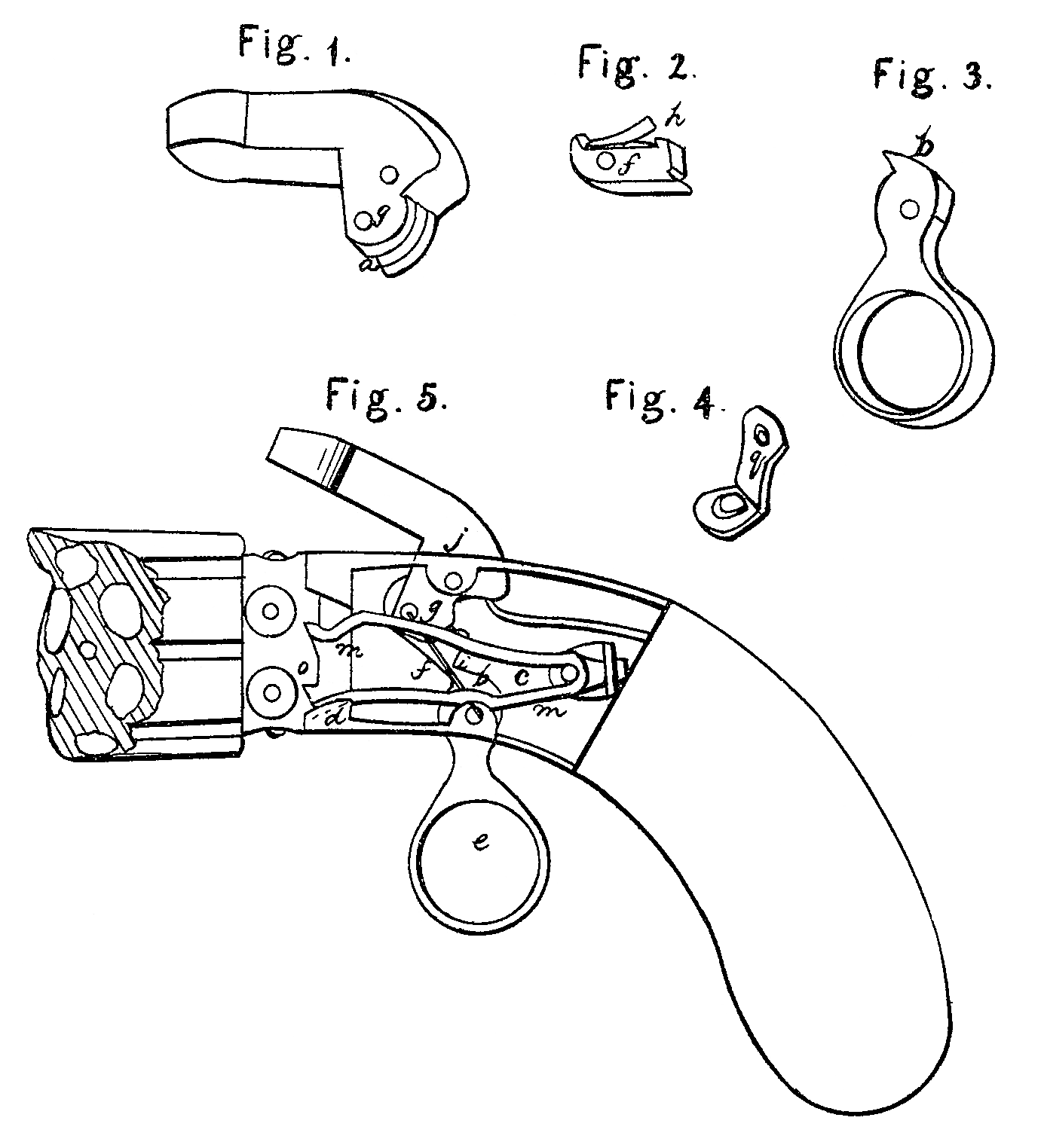
Figure 1 is a view of the hammer, the lower part of which is generally used as the tumbler, but shown here with a slot at a to receive the fly-tumbler, (shown at Fig. 2,) which has a hooked projection at one end for the purpose of catching upon the side of the hammer and causing the hammer and tumbler to become as one, both of which must move together when the trigger is drawn backward. On the opposite end of the fly-tumbler is a groove for the purpose of receiving the sear, as hereinafter described. Fig. 3 is the trigger, the upper end of which, at b, is the sear. Fig. 5 is a view of the whole lock, containing its different parts in their proper places.
The following is a description of the operation of the different parts by which each is made to perform its respective duties.
In Fig. 5, if the trigger e is drawn back it will press the Sear b against the back part of the fly-tumbler, (shown at f) this fly-tumbler being in connection with the lower part of the hammer, (formerly described by Figs. 1 and 2, where it is shown that the slot in the lower part of the hammer is to receive the fly-tumbler,) and fastened by a pin at g and allowed to work easy, so as to be pressed down by the small spring shown at h upon the fly-tumbler at Fig. 2. Thus the fly-tumbler f being connected with the hammer by the ping and the hooked projection, the hammer must raise.
When the trigger is drawn to a certain distance back the sear b Will catch in a niche or groove formed in the back part of the fly-tumbler, as it i, in which position it is shown in the drawings. In this position it may be left, and cannot return of itself for the reason of its having passed its center-ping, upon which the whole works, which may be understood by examining the drawings. It is shown by the red line, which shows its center, after it passes which it cannot return; but if the operator wishes he may lower the hammer very gently by slowly pressing forward the trigger, when the hammer will be gently lowered and everything will be in its former position; but if a discharge is Wanting, the trigger must be drawn a little farther back. Then the sear will pass the niche in the fly-tumbler and the hammer will strike a sharp blow, after which all that is necessary is to press forward the trigger, and it will raise the fly-tumbler, after it passes which the tumbler falls to its former position. By means of the spring h, between it and the upper part of the slot in the hammer, when this is done the whole is ready for a second operation.
The following is the mode of revolving the barrels: In Fig. 5 may be seen a large spring, n, which may be of most any shape. This spring, by being pressed together and allowed to expand, causes the barrels to revolve. This is operated in the following manner: When the trigger is drawn backward and a blow is given by the hammer, the hammer in descending causes a projection formed on the side of the lower part of the hammer (or the ping, which may be left too long and form a projection) to press upon the spring. Thus the end of the spring is lowered down to o, one ratchet lower, and the spring presses forward, occasioned by the other end of the spring at d being bent downward and working in a groove, d, thus causing the other end to catch the ratchet at o, and when the hammer is again cocked the pin g is again raised, allowing the cocked the ping is again raised, allowing the ratchet at o and revolves the barrels around to the proper place to receive a blow from the hammer. Fig. 4 is a small piece of steel or spring, which is placed at the farther end of the spring in and contains a hole at g to receive the end of the spring, which is for the purpose of keeping the spring in in its proper place, and also presses it forward in case the bend in the end of the spring working in the groove at d should fail to perform its part.
What I claim as my invention is—
The fly-tumbler arranged and combined with respect to the sear and cock in the manner and for the purposes set forth in my specification.
STANHOPE W. MARSTON.
Witnesses:
John R. Smith,
William D. Stivers.