
US 8412
UNITED STATES PATENT OFFICE.
JOSEHUA STEVENS, OF CHICOPEE, MASSACHUSETTS, ASSIGNOR TO MASSACEHUSETTS ARMS COMPANY.
IMPROVEMENT IN REVOLVING-BREECH PISTOLS.
Specification forming part of Letters Patent No. 8,442, dated October 7, 1851.
To all whom it may concern:
Be it known that I, Joshua Stevens, of Chicopee, in the county of Hampden and State of Massachusetts, have invented one or more certain new and useful Improvements in Repeating Pistols or Fire-Arms; and I do hereby declare that the same is fully described and represented in the following specification and accompanying drawings, letters, figures, and references thereof.
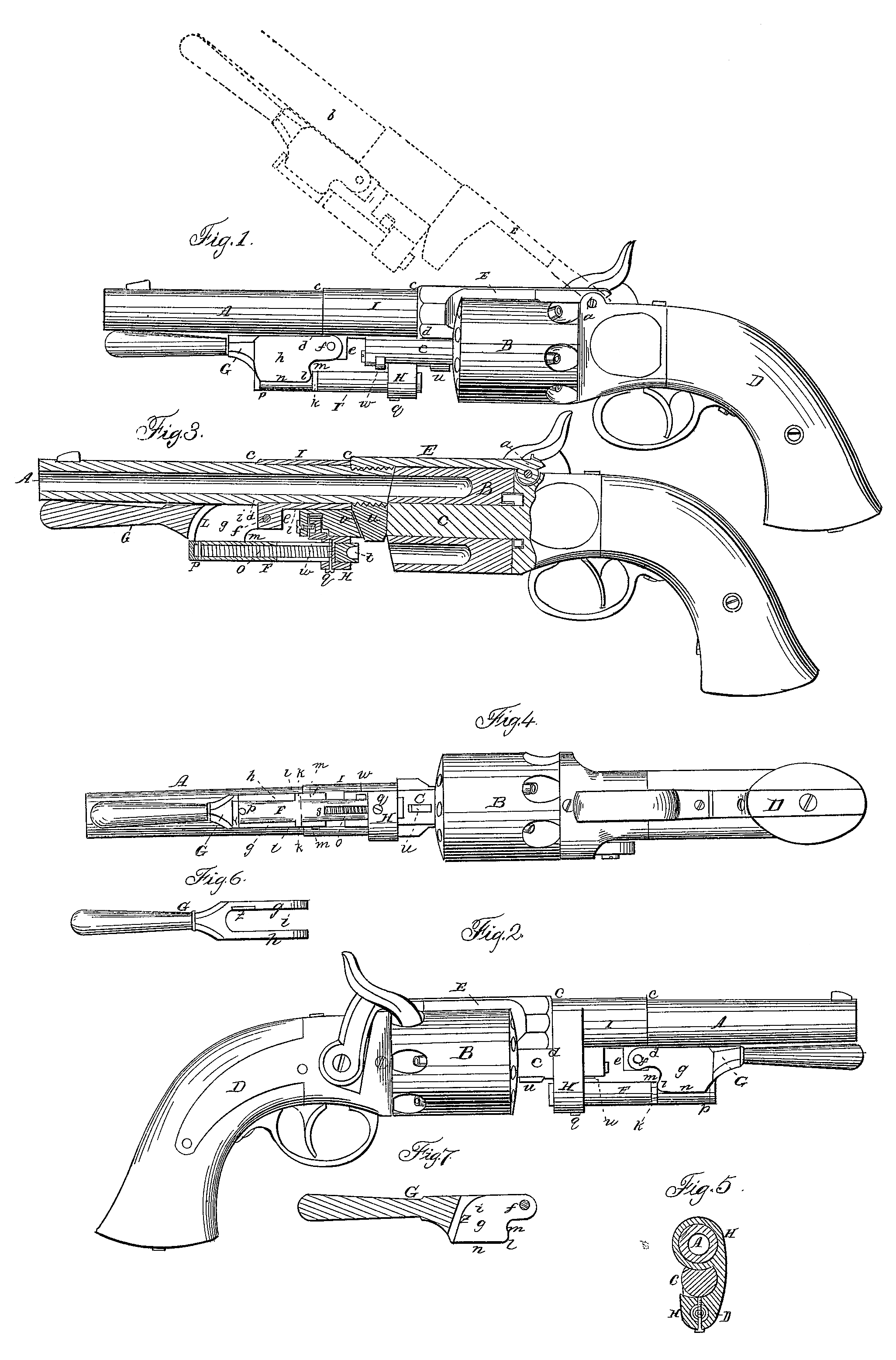
Of the said drawings, Figure 1 denotes a side view of a revolver or repeating pistol constructed on my improved plan. Fig. 2 is a view of the opposite side of it. Fig. 3 is a vertical longitudinal and central section of it. Fig. 4 is an under side view of it. Fig. 5 is a transverse section of it, taken through the latch-hook, to which reference will be hereinafter had.
In the said drawings, A represents the barrel; B, the chambered cylinder; C, the arbor on which said cylinder is supported, and on which it is made to revolve. D is the stock, from which the arbor projects.
As the lock, as well as the mechanism for revolving the chambered cylinder, forms no part of my present invention, it will not be necessary for me to enter into any description of them.
The barrel A is connected to the stock by means of a bar or piece of metal, E, which is hinged or jointed at one end to the stock, while at its other end it is fastened firmly to the barrel. The hinge or joint a of the part E is so made as to enable the said part E and the barrel to be turned up into the position denoted at b by the dotted lines in Fig. 1.
For forcing the balls into the chambers I employ a rammer, F, and a lever, G. The rammer has a cylindrical. shape externally, and is supported by and made to slide freely in a longitudinal direction, through a latch – hook, H, which swivels or turns upon the barrel A and hooks around the arbor C.
On and around the barrel, and concentrically with it, is a swivel-tube, I, which turns loosely on the barrel, and is kept in position by shoulders c, d, or other analogous contrivances at its extremities. . From this swivel-tube the latch-hook H projects, as seen in the drawings. The fulcrum end of the lever G is jointed or hinged to this swivel-tube, and by means of a projection, e, therefrom, the lever embracing the projection, and turning on a pin, f, extending through it and the projection. An upper side view of this lever is seen in Fig. 6. The said lever is formed or made with two flat cheeks, g h, arranged parallel to one another, and with a space, i, between them wide enough to receive the rammer F, as seen in the drawings, and to allow it to work through the lever while the lever is being turned down toward a right angle with the barrel. The rammer has a projection, k, formed on one or both sides of it, and to operate in connection with a rounded corner or cam, l, made on the adjacent cheek of the lever. Above this cam the lever is provided with a square or other proper-shaped shoulder, m, which stands at, or about at, right angles to the outer edge, n, of the cheek, and with respect to the fulcrum of the lever, as seen in the drawings.
The rammer is made hollow, and to contain a helical spring, o, one end of which bears against a head or plug, p, inserted in the outer end of the rammer. The other end of the spring rests against a screw-pin, q, which passes through the latch-hook and the rammer, and long slots r s made through the latter, as seen in the drawings. That end of the rammer which is nearest to the chambered cylinder B may be made solid, and with a sunken cavity or space, t, for the ball to project in when forced into the chamber destined to receive it. In order to steady the barrel in lateral directions, it has a tenon, u, extended from it and made to enter a corresponding mortise, v, made down through that part of the arbor, which projects beyond the chambered cylinder B. Besides the above, the arbor is provided with a small thumb spring-catch, w, to catch into the latch-hook and prevent it from slipping off the arbor when it is turned down to its lowest position. Neither the thumb-catch nor the hook is a new contrivance, and so far as they are concerned they may be said to differ from my present improvement.
There is a small projection, y, formed on the side of the head or outer end of the rammer, which projection extends over a curved cam, z, formed on , the inner surface of the cheeks of the lever, as seen in Figs. 6 and 7, which are a longitudinal and vertical section of the lever. This cam should be so made as to enable a person, by means of the lever, to effect the return or entire outward movement of the rammer in case any dirt or carbonaceous or extraneous matter on the surface of the rammer should produce sufficient friction to overcome the expansive force of the spring contained in the rammer. By means of the peculiar construction of the lever, and particularly in consequence of the addition to it of the shoulder for the projection on the rammer to bear against, the lever is forced and held up against the barrel while not being used to cause a movement of the rammer. Besides the power of the spring acting to expel the rammer from the chamber of the cylinder, there is a self-adjusting power or mechanism brought into operation to further move the rammer and lever and hold the lever up against the barrel. This new element or part of the mechanism dispenses with any spring-catch, as usually applied and used on the extreme outer end of the lever, and made to act against a stud or projection from the barrel.
By combining both the lever and the latch hook or support of the rammer with the barrel by means of a single swivel-tube or any analogous contrivance not only the latch-hook but the rammer may be moved out of the way of the arbor in such manner as to enable the barrel to be elevated into the position denoted by dotted lines in Fig.1, and so as to render it easy to remove the chambered cylinder from the arbor.
I do not claim to make the latch-hook alone revolve on the barrel; but
I claim—
The improvement of so connecting or combining the latch-hook, the slide-bearing of the rammer, and the lever with the barrel by means of the swivel-tube, or any analogous contrivance as to enable them to be all simultaneously turned laterally or revolved around the axis of the barrel, and thereby remove any obstruction to the elevation or upward movement of the barrel, such as may be necessary in order to effect the removal of the cylinder of charging-chambers from the arbor on which it is supported.
In testimony whereof I have hereto set my signature this 25th day of June, A.D. 1851.
JOSHUA STEVENS.
Witnesses:
E. W. B. Holcomb,
F. W. Carter.