
US 30602
UNITED STATES PATENT OFFICE.
JOHN ADAMS, OF DALSTON, COUNTY OF MIDDLESEX, ENGLAND, ASSIGNOR TO THOMAS POULTNEY, OF BALTIMORE, MARYLAND.
IMPROVEMENT IN REVOLVER FIRE-ARMS.
Specification forming part of Letters Patent No. 30,602, dated November 6, 1860.
To all whom it may concern:
Be it known that I, John Adams, of Dalston, in the county of Middlesex, in that part of the United Kingdom of Great Britain and Ireland known as “England,” have invented certain new and useful Improvements in Revolver Fire-Arms; and I do hereby declare that the following is a full, clear, and exact description of the same, reference being had to the accompanying drawings, forming part of this specification, in which—
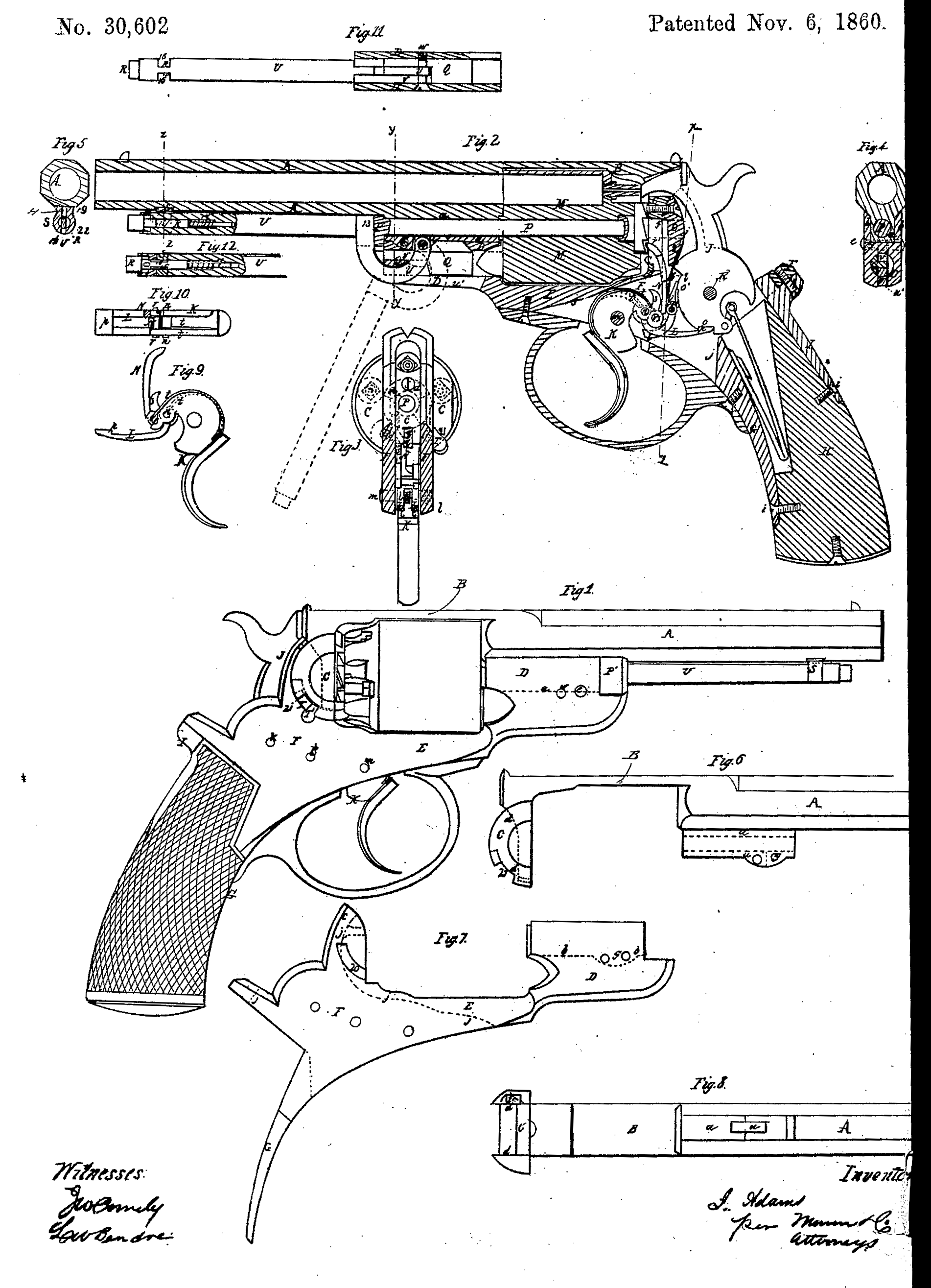
Figure 1 is a side view of a pistol with my improvements. Fig.2 is a longitudinal section of the same. Fig. 3 is a transverse section of same in the plane indicated by the line x x in Fig. 2, omitting the hammer. Fig. 4 is a transverse section of the same in the plane indicated by the line y y in Fig. 2. Fig. 5 is a transverse Section of the same in the plane indicated by the line 22 in Fig. 2, Figs, 6 and 7 are side views of the two pieces of which the body of the pistol is composed. Fig.8 is an under side view of the piece represented in Fig.6. Fig. 9 is a side view of the trigger and the parts attached thereto. Fig.10isatop view, corresponding with Fig. 9. Fig.11 is a longitudinal sectional view of the rammer as seen from the upper side, showing its operating-lever entire. Fig. 12 is a longitudinal section of part of the rammer-lever parallel with the plane of section of Fig. 1.
Similar letters and numbers of reference indicate corresponding parts wherever they occur in the several figures.
My invention relates to revolver fire-arms of that kind whose chambers are in a cylinder rotating on an axis parallel with the bore of a fixed barrel.
My first improvement consists in a certain improved construction of the body of the arm, whereby great strength is obtained and facility is afforded for slotting and drilling out for the reception of the lock and rammer.
My second improvement consists in a certain improved construction of and mode of applying and combining the several parts of the lock for the purpose of enabling the hammer to be raised and let fall by one pull of the trigger for rapidly-repeated firing, or to be cocked by hand and only let off by the trigger, as in the older kinds of fire-arms for firing more deliberately and with more accurate aim, the object of this improvement being more especially to bring the parts of the lock for the above purpose into such relation as to enable them to be brought within a parallel slot cut in the body of the arm to be inserted and taken out without difficulty.
To enable those skilled in the art to make and use my invention, I will proceed to describe its construction and operation.
In the construction of the body of the arm I make the barrel A, the top strap, B, and the recoil-plate C in one piece, as shown in Figs. 6 and 8, and make the part D of the cylinder-frame that is below the barrel and in front of the cylinder, the bottom strap, E, of the cylinder-frame, the lock-frame F, and the bottom strap, G, of the stock in another piece, as shown in Fig. 7. This construction is to some extent shown in Figs. 1, 2, 3, and 4, the section of the piece ABC being tinted blue and that of the piece D E F G tinted yellow in Figs. 2, 3, and 4, for the sake of distinction.
On the bottom of the barrel I provide a tenon, a, (see Figs. 2, 4, 6, and 8,) to fit a mortise, b, (see Figs. 4 and 7,) and on the upper part of the lock-frame I provide a tenon, c, (see Figs. 2 and 7,) to enter a mortise, d, (see Figs. 6 and 8,) in the back of the recoil-plate. These mortises and tenons enable the two pieces to be secured together by two screws, e and f, of which e passes transversely through a hole, g, in the tenon a and mortise b and screws into one side of the said mortise, and f passes through the tenon ( from the back and screws into the recoil-plate C.
The stock H is fitted and secured by screws i and i’ between the strap G and a strap, I, that is secured by a screw, h, to the back of the lock-frame. The piece D E F G has cut in it a parallel-sided slot, j j, to receive the hammer and the other parts of the lock. This slot, besides being shown in the sectional views Figs. 2 and 3, has its form represented by dotted lines in Fig. 7.
J is the hammer, fitted to the slot j j and working on a pin, k, inserted transversely through the body of the arm.
l is the sear, made in the form of a lever and working on a fixed pin, l’.
q is the sear-spring, attached by a screw, q’, to the back of the tenon c.
K is the trigger, fitted to the slot j and working on a fixed pin, m.
L is a link, having its front end attached to the trigger by a pin-joint, n, and having formed on its rear end a catch, p, to enter a notch, o, formed in the bottom of the hammer-butt. By drawing back the trigger when the hammer is down the link is made to raise the hammer, and when the hammer is raised to its full height, and its full-cock notch o’ has passed the point of the sear, the catch p is forced out of the notch o by the action of the extremity of the link. L against the hammer, and in consequence of the trigger having by its action on the lower end of the sear brought the point of the latter clear of the notch o’ the hammer falls.
The sear works through a slot provided for it in the link L, which is of nearly the full width of the slot j j in the body of the arm. When the hammer is drawn back to cock it by the direct application of the hand to it the back of the notch o, by its action on the extremity of the link L, forces forward the upper part of the trigger and draws back the finger-piece thereof, but when the hammer is liberated the sear falls into the notch o’, for if the hammer is drawn back far enough to bring the sear out of range of the notch on the liberation of the hammer from the hand the sear-spring forces the sear toward the notch as the hammer begins to move down, and so stops it; but on the application of a slight pressure of the finger to the trigger the sear is made to leave the notch and the hammer falls.
The dog N, by which the rotation of the cylinder M is effected, is attached to the trigger by a pin-joint, r, and works through a narrow slot, r;, in the recoil-plate; and the cylinder-stop s is attached rigidly to the trigger, and these operate whether the hammer is drawn back by the action of the trigger or by the direct application of the hand itself, as in either case the hammer and trigger move together.
The link L and the dog N are both kept to their work by a single Spring, t, one end of which is secured to the trigger and the other end divided into two parts— one to press, upon the link and the other upon the dog.
P is the cylinder axis-pin, passing through a hole provided for it in the body of the arm, through the central bore of the cylinder M, and into a hole in the recoil-plate. This pin, which is inserted from the front, has a head, P’, at its frontend to prevent it entering farther into the recoil-shield than is desired, and this head is fitted to the body of the arm in such a manner as to prevent its turning.
Q is the rammer, working through a hole in the body below the cylinder axis-pin.
u is a slot in the body between the two holes which receive the rammer and the cylinder axis-pin for the reception of the end of the rammer-lever U; and it is a slot provided in the body below the hole in which the rammer works for the lever U to work in. The rammer has a slot or recess, v, provided in it for the lever to pass through. The lever is made with an elbow, 13, (see Fig. 2,) and from the elbow, to the extremity which is attached to the body by its fulcrum-pin w, it is of curved form. The fulcrum-pin passes through the body and crosses the slot u. In moving the lever toward and from the barrel its curved portion has a cam-like action upon the rammer, and moves it toward and from the cylinder. When the lever lies close under the barrel the rammer is held some distance clear of the cylinder, and the elbow 13 of the lever bears against the head of the cylinder axis-pin P, and so secures the said pin in place; but by the downward movement of the pin the rammer is forced back into the chamber, which is at any time in line with it, and the pin P is liberated, so that it can be drawn out.
The front end of the lever is secured to the barrel when the rammer is not in use by a small sliding bolt, R, which is fitted into the said lever, and a catch, S, under the barrel. (Shown in Figs. 1, 5, 11, and 12.) The body of the said bolt is of cylindrical form, and it has a notch, 15, cut in each side to correspond with notches 16, cut in opposite sides of the lever, such notches making the bolt and lever flat in one place, and the said bolt has a spring, 17, applied to it within the lever in such a manner as to exert a constant tendency to force it outward from the lever as far as is permitted by a pin, 18, which prevents it from being forced out entirely.
The catch S has a circular opening, 22, through it of the full size of the body of the bolt, and a narrow slot, 19, above and below the said opening wide enough to receive the flattened portions of the lever and bolt, the said slot being open at the bottom, as shown in Fig. 5. The notches in the bolt are beveled on the sides farthest from the end of the lever. As the lever is moved up to the barrel the flattened portion of the lever passes into the catch S, and the beveled sides of the notches in the bolt come in contact with the back of the catch, and so allow the bolt to slip thereinto, and as soon as the bolt arrives within the circular portion of the catch, which is when the lever arrives in contact with the barrel, it (the bolt) is driven forward by the spring and locks the lever.
To unlock the lever it is only necessary to press back the head of the bolt which projects from the head of the lever, and the lever may be then moved downward from the barrel.
T is the safety-bolt by which the cylinder is locked when it is not required to use the arm formed to slide in a circular course through the recoil shield. It is fitted into an arc-formed groove, 20, (see Fig. 7,) in one side of the lower piece of the body, and is kept in place by the corresponding side of the recoil-plate C when the two pieces of the body are together. A notch, 21 (see Figs. 1, 6, and 8,) is made in the shield for the passage of the projecting knob T’, by which the bolt is worked. The bolt may act in one of a series of notches specially provided in the cylinder for the purpose, or may operate in one of the notches in which the nipples are received.
What I claim as my invention, and desire to secure by Letters Patent, is—
1. The construction of the body of a revolver of two pieces of the form described, fitted and secured together substantially as herein specified.
2. The link L, constructed and applied in combination with the trigger and operating in combination with the notch o of the hammer, substantially as herein set forth.
3. In combination with the link L, applied as described, the arrangement of the cocking dog and the sear, substantially as herein described.
JOHN ADAMS.
Witnesses:
Julien Rawlinson,
William Bibly.