
British 1889
A.D. 1865, 20th July. Nº 1889.
Fire-arms and Cartridges.
LETTERS PATENT to William Tranter, of Birmingham, in the County of Warwick, Gun Maker, for the Invention of “IMPROVEMENTS IN FIRE-ARMS, AND IN CARTRIDGES FOR THE SAME.’
Sealed the 12th January 1866, and dated the 20th July 1865.
PROVISIONAL SPECIFICATION left by the said William Tranter at the Office of the Commissioners of Patents, with his Petition, on the 20th July 1865.
I, WILLIAM TRANTER, of Birmingham , in the County of Warwick, Gun Maker, do hereby declare the nature of the said Invention for “IMPROVEMENTS IN FIRE ARMS, AND IN CARTRIDGES FOR THE SAME,” to be as follows:—
My Invention consists in the first place in adapting and applying to breach-loading guns and pistols a lever working on the bottom or side of the body or breach piece of the same, and taking into the piece fixed to the barrel or barrels, and working in the body for the purpose of fixing the barrels in their place therein with facility, also a slide working on the under side of the barrels to draw out the empty shells of the cartridges from the barrels, such slide having wings or projections upon its end for taking hold of for the purpose. The parts of the gun or pistol are arranged so that the stock is brought conveniently within the grasp of the band, and the lock caused to rest firmly thereon, thereby diminishing the ordinary tendency to interfere with the aim by the overhanging of the barrel. In the case of a double pistol the locks are arranged with a plate which is solid with the body, and is in the middle of the pistol, with a hollow peg for carrying the two hammers, and fixing the side pieces to the body of the pistol.
My Invention consists in the second place in the use of a plunger working in a line with the barrel, and fixed as required by means of a handle with a projection or projections acting on the plunger for locking the same in its place, which handle may be made to work either concentrically or excentrically with or in relation to the plunger, or the plunger may be fixed as required by means of a slide working at nearly a right angle a short distance from the front of the plunger. Part of the lock of this gun will be made to work in-connection with the plunger, by moving a striking pin in the centre of the plunger, such pin being acted upon by a spiral spring for the purpose of striking the cartridge hereafter described.
My Invention consists in the third place in forming cartridges with a piece of metal at the base strong enough to resist the blow from the striker, and formed to receive a cap placed on the end when required to be fired, or the fulminating powder may be enclosed in the centre.
And my Invention relates in the last place to breach-loading revolvers, and consists in forming the chambers with a breach piece for closing the ends of the chambers, which piece revolves on the centre rod. The chambers are fixed or locked on this breach piece and caused to revolve simultaneously with it. The chambers will be free to revolve on the breach piece when required to be loaded or unloaded. The chambers will be fixed to the breach piece by means of a slide or hinge joint and a screw at the front.
SPECIFICATION in pursuance of the conditions of the Letters Patent, filed by the said William Tranter in the Great Seal Patent Office on the 20th January 1866 .
TO ALL TO WHOM THESE PRESENTS SHALL COME, I, William Tranter, of Birmingham, in the County of Warwick, Gun Maker, send greeting.
WHEREAS Her most Excellent Majesty Queen Victoria, by Her Letter Patent, bearing date the Twentieth day of July, in the year of our Lord One thousand eight hundred and sixty-five, in the twenty-ninth year of Her reign, did, for Herself, Her heirs and successors, give and grant unto me, the said William Tranter, Her special licence that I, the said William Tranter, my executors, administrators, and assigns, or such others as I, the said William Tranter, my executors, administrators, and assigns, should at any time agree with, and no others, from time to time and at all times thereafter during the term therein expressed, should and lawfully might make, use, exercise, and vend, within the United Kingdom of Great Britain and Ireland, the Channel Islands, and Isle of Man, an Invention for “IMPROVEMENTS IN FIRE-ARMS, AND ON CARTRIDGES FOR THE SAME,” upon the condition (amongst others) that I, the said William Tranter, my executors or administrators, by an instrument in writing under my, or their, or one of their bands and seals, should particularly describe and ascertain the nature of the said Invention , and in what manner the same was to be performed, and cause the same to be filed in the Great Seal Patent Office within six calendar months next and immediately after the date of the said Letters Patent.
NOW KNOW YE, that I, the said William Tranter, do hereby declare the nature of my said Invention, and in what manner the same is to be performed, to be particularly described and ascertained in and by the following statement, reference being had to the Drawing hereunto annexed, and to the letters and figures marked thereon ( that is to say):—
My Invention of “improvements in fire-arms and in cartridges for the same” consists in the first place in adapting and applying to breech-loading guns and pistols a lever working on the bottom or side of the body or breech piece of the same, and taking into the piece fixed to the barrel or barrels, and working in the body for the purpose of fixing the barrels in their place therein with facility, also a slide working on the under side of the barrels to draw out the empty shells of the cartridges from the barrels, such slide having wings or projections upon its end for taking hold of for the purpose. The parts of the gun or pistol are arranged so that the stock is brought conveniently within the grasp of the hand, and the lock caused to rest firmly thereon, thereby diminishing the ordinary tendency to interfere with the aim by the overhanging of the barrel. In the case of a double pistol the locks are arranged with a plate which is solid with the body, and is in the middle of the pistol, with a hollow peg for carrying the two hammers, and fixing the side pieces to the body of the pistol.
My Invention consists in the second place in the use of a plunger working in a line with the barrel, and fixed as required by means of a handle with a projection or projections acting on the plunger for locking the same in its place, which handle may be made to work either concentrically or excentrically with or in relation to the plunger; or the plunger may be fixed as required by means of a slide working at nearly a right angle a short distance from the front of the plunger. Part of the lock of this gun will be made to work in connection with the plunger by moving a striking pin in the centre of the plunger, such pin being acted upon by a spiral spring for the purpose of striking the cartridge hereafter described.
My Invention consists in the third place in forming cartridges with a piece of metal at the base strong enough to resist the blow from the striker, and formed to receive a cap placed on the end when required to be fired, or the fulminating powder may be enclosed in the centre.
And my Invention relates in the last place to breech -loading revolvers, and consists in forming the chambers with a breech piece for closing the ends of the chambers, which piece revolves on the centre rod. The chambers are fixed or locked on this breech piece when required to be loaded or unloaded. The chambers will be fixed to the breech piece by means of a slide or hinge joint and a screw at the front.
Having thus stated the nature of the said Invention, I will proceed to describe more particularly in what manner the same is to be performed by reference to the accompanying Drawings, in which are represented the parts of fire-arms and cartridges above referred to.
DESCRIPTION OF THE DRAWINGS.
Figures 1 to 5 relate to the first part of my Invention. Fig. 1 represents a single-barrelled pistol, with my improvements applied thereto, shewing the barrel fixed ready for firing ; Fig 2 shews the same with the barrel opened for loading; Fig. 3 represents a part of the barrel with the slide for drawing out the empty shells of cartridges applied thereto; Fig 4 is an end view of the same ; and Fig. 5 is a plan or horizontal view of the slide. In these several Figures the same letters of reference indicate corresponding parts.
A is the stock, and B the lock of the pistol, which are constructed and arranged as shewn for the purpose of bringing the stock conveniently within the grasp of the hand, and causing the lock to rest firmly thereon, and thereby to diminish the tendency to interfere with the aim by the overhanging of the barrel, which is usual with the ordinary construction and arrangement of those parts.
C is the barrel; D, the cock or hammer; E, is a lever working on a pivot fixed as shewn in the lower part of the body or breech piece; this lever is formed with a hooked end at its upper part, which takes into the piece F fixed to the barrel, and thereby locks the barrel, as shewn by dotted lines in Fig. 1, the lever being kept in its position by a spring as shewn. When it is described to liberate the barrel the lower end of the lever is pressed inwards into the position shewn in Fig. 2, by which movement the hooked upper end of the same is thrown back so as to disengage the piece F, and allow the barrel to be opened as shewn. G is a slide formed with a slot, as shown in Fig. 5, to admit of its being slidden along the piece F, which fits the slot, the slide being kept to the under side of the barrel by a pin passed through the piece F, as shewn in Fig. 4. This slide is pressed inwards into the position shewn in Fig. 2 5 when the barrel is to be closed, and it is drawn outwards into the position shewn in Fig. 3 for drawing out the shells of empty cartridges from the barrels. H, H, are wings or projections on the end of the slide for the purpose of taking hold of it as required.
When my Invention is applied to a double-barrelled pistol the lock is arranged with a plate which is solid with the body, and is in the middle thereof, so as to admit of the two hammers being arranged one on each side of it. The hammers work on a hollow peg screwed and fixed in the said plate, and the side pieces are fixed to the body of the pistol by means of a pin passing through the said hollow peg. In this case the slide for withdrawing the 15 cartridge cases is adapted for drawing out the two cases at once, the lever for fixing the barrels being the same as above described.
Fig. 6 is a section of a portion of a gun with the improvements referred to under the second head of my Invention adapted and applied thereto. These improvements consist of a tube I, into the end of which the barrel is screwed. This tube is formed with a solid piece K and an enlarged end and tang L, for fixing to the stock and guard plate, and also with a slot at the top for the purpose of loading, and a continuation of the same slot at the top for the projections on the plunger M, and also a corresponding slot at the bottom for the projections on the striking pin N to work in as required; part of the slot at the top of the tube has a piece O jointed to it, and inserted in it to form a stop in order to prevent the plunger M from being drawn too far back, and to admit of the plunger being withdrawn when required for cleaning. The tube is also hollowed out to admit of the plunger M being locked by means of the projections thereon. The plunger M is formed with a handle at M* (not shewn in the Drawing), for the purpose of moving it as required. The end of the plunger M is formed into a hollow to act as a clip P for withdrawing the cartridge case. The plunger is also formed with a hole in the direction of its length for the purpose of carrying the striking pin N, and the hole is enlarged at the rear end of the plunger in order to give space for the action of the spiral spring on the striking pin N. A slot is formed on the under side of the plunger at its rear end, in order to give space for the piece Q formed on the striking pin N to work in. The rear end of the plunger is closed by means of a screw R, having a hole through it which serves as a guide for the striking pin N. The striking pin N is formed with a piece Q on its under side, which piece Q is formed with notches for the sear S to take into for the purpose of retaining the striking pin either at cock or half cock. Tis a knob screwed on the end of the striking pin N for the purpose of pulling it into full cock. The sear S is acted upon as required by means of a spring as shewn. The guard is adapted as shewn to give strength and stability to the gun.
Fig. 7 is an end view, and Fig. 8 a longitudinal section of a cartridge constructed as referred to under the third head of my Invention with a piece of metal a at the base strong enough to resist the blow from the striker. The central portion of the piece a is formed to receive a percussion cap as shewn. The mode of fixing the shell b to the base may be varied from that shewn in the Drawing. The piece a is formed with a flange on its extreme base to prevent its being driven into the barrel. A hole for firing may be formed either through the central portion of the piece, or one or more holes on each side of it.
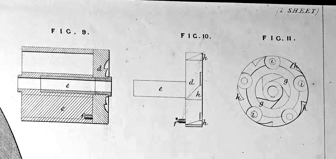
Fig. 9 is a longitudinal section of a revolving chamber c with its end closed by a breech piece d, which revolves on the centre rod not shewn in the Drawing. The chamber c requires to be hollowed out at its rear end to afford space for the insertion of the socket part of the breach piece d. The breech piece d is formed with a socket e, which revolves on the centre rod, and is caused to revolve with the chamber by the stud pin f, fixed in the breech piece, taking into a corresponding hole formed in the chamber. A screw is inserted in the front of the breech piece for the purpose of fixing the chamber as required in the frame of the pistol, such screw having a hole in the centre for the centre rod to pass through.
Fig. 10 is a side view, and Fig. 11 a front view of the breech piece. The ratchet g causes the breech piece and chamber to revolve, and the notches h, h, are for the purpose of stopping the chamber during its revolution in the required position for firing. The chambers are fired by means of sliding pegs i, i, inserted opposite the firing point of each cartridge.
Having thus described the nature of the said Invention, and in what manner the same is to be performed, I hereby declare that what I claim as of my Invention is,—
First, the construction of breech -loading guns and pistols with a lever for fixing the barrels in the manner described, also with a slide for withdrawing cartridge cases as described, and also with the parts arranged so as to avoid interference with the aim in the manner described.
Secondly, the construction of guns with a plunger and striking pin combined with the other parts, and adapted for working as described.
Thirdly, the construction of cartridges with a piece of metal
at the base strong enough to resist the blow from the striker, as represented and described.
And, lastly, the combination of the breech piece with the revolving chamber, in the manner and for the purpose described.
In witness whereof, I, the said William Tranter, have hereunto set my hand and seal, the Twentieth day of January, in the year of our Lord One thousand eight hundred and sixty-six.
WILLIAM TRANTER. (L.S.)
Witness,
William Spence,
8, Quality Court,
Chancery Lane.