
British 2113
A.D. 1866, 17th August. N° 2113.
Fire-arms.
LETTERS PATENT to William Tranter, of Birmingham, in the County of Warwick, Gun Maker, for the Invention of “Improvements in Fire-arms.”
Sealed the 11th December 1866, and dated the 17th August 1866.
PROVISIONAL SPECIFICATION left by the said William Tranter at the Office of the Commissioners of Patents, with his Petition, on the 17th August 1866.
I, WILLIAM TRANTER, of Birmingham, in the County of Warwick, Gun Maker,do hereby declare the nature of the said Invention for “IMPROVMENTS IN FIRE-ARMS,” to be as follows:—
My Invention relates in the first place to rifle guns constructed similar to those described in the Specification of a Patent granted to me bearing date 20th July 1865, No. 1889,or guns with a plunger moving backwards and forwards for the purpose of loading and unloading, and consists in adapting and applying thereto an extractor for withdrawing cartridge cases, such extractor being formed with a piece of tube cut open on one side in order to fit more readily into a recess formed in the front of the plunger,and having two longitudinal grooves for the purpose of holding two springs or lugs intended to take hold of the hinder part of the cartridge case; these springs or lugs are also made to work in suitable grooves formed in the breech piece, which will prevent the extractor from turning on its axis. The extractor above referred to may be varied by making the tube without cutting a piece out in the side, as in the former instance, but with two longitudinal grooves for carrying the springs or lugs as before; this extractor may be fastened to the plunger by means of a collar or washer and one or more screws, or by means of a vertical pin. The extractor may also be formed as a cap with a screw cut inside in order to fit on to a corresponding screw cut on the front part of the plunger. The end of the cap has a small hole formed in it for the striking pin to work through. The springs or lugs for these extractors may be constructed in one piece with a socket or ring at the rear end, a suitable recess being formed on the end of the tube of the extractor for the socket or ring to fit upon.
My Invention consists in the second place in adapting and applying to the lower part of the breech piece a lever, which I call a thrower, for the purpose of throwing out the cartridge case; this thrower is a lever with a fulcrum at the rear end, and is turned up at the front end to strike the cartridge case, the rear end being also turned up in order that a projection on the plunger when the same is withdrawn may strike such rear end of the lever and raise the front end to throw out the cartridge case. The lever is formed with a fork where it works on its fulcrum , so as to admit of its being removed by the fingers only when required; this lever or thrower is made to act in connection with the extractor above described.
My Invention has reference in the third place to a portion of the Invention described in the Specification of the Patent above referred to, and relates to the lever for fixing the barrel, which lever I place at the upper part of the slot in which it works, instead of in the lower part thereof as in my former Patent, such lever taking into a notch formed in the block fixed to the barrel for the purpose of fixing the barrel firmly to the frame. I form a stop for the barrel by means of a pin acting against a book formed on the said block and placed at right angles to the slot in which the block moves. The extractor for the cartridge for this gun or pistol has the slot so formed at the front that the hammer can strike all across, a projecting piece being left on the end of the barrel and corresponding with the slot in the extractor.
My Invention consists in the fourth place in adapting and applying a lever similar in principle to that last described to sporting arms. For this purpose I vary the form of the lever and make one part of it act in connection with an extractor either directly or with a connecting link; by this means the extractor will be caused to return to its position in the barrels for loading while the barrels are in an elevated position.
My Invention consists in the fifth place in making the striking pin for igniting cartridges which fire in the centre in a curvilinear instead of a straight line as usual, and moving in a curvilinear slot formed in the breech piece.
My Invention consists in the sixth place in the combination of a lifting catch, having a book on the end acting in a slot formed in the hammer, with a catch or sear for acting in connection therewith placed at top of the slot in the body, the top or hook of the lifting catch acting underneath the sear for the purpose of releasing it from the catch in the hammer.
And my Invention consists in the last place in forming a spring to act upon the lifting catch and lifter simultaneously; the spring is fixed to the top part of the lifting catch and extends round the bottom of the same, being bent at the end in such a manner as to act on the lifter.
SPECIFICATION in pursuance of the conditions of the Letters Patent, filed by the said William Tranter in the Great Seal Patent Office on the 15th February 1867.
TO ALL TO WHOM THESE PRESENTS SHALL COME, I, William Tranter, of Birmingham , in the County of Warwick, Gun Maker, send greeting.
WHEREAS Her most Excellent Majesty Queen Victoria, by Her Letters Patent, bearing date the Seventeenth day of August, in the year of our Lord One thousand eight hundred and sixty -six, in the thirtieth year of Her reign, did, for Herself, Her heirs and successors, give and grant unto me, the said William Tranter, Her special licence that I, the said William Tranter, my executors, administrators, and assigns, or such others as I, the said William Tranter, my executors, administrators, and assigns, should at any time agree with, and no others, from time to time and at all times thereafter during the term therein expressed, should and lawfully might make, use, exercise, and vend, within the United Kingdom of Great Britain and Ireland, the Channel Islands, and Isle of Man, an Invention for “IMPROVEMENTS IN FIRE-ARMS,” upon the condition (amongst others) that I, the said William Tranter, my executors or administrators, by an instrument in writing under my, or their, or one of their hands and seals, should particularly describe and ascertain the nature of the said Invention, and in what manner the same was to be performed, and cause the same to be filed in the Great Seal Patent Office within six calendar months next and immediately after the date of the said Letters Patent.
NOW KNOW YE, that I, the said William Tranter, do hereby declare the nature of my said Invention, and in what manner the same is to be performed, to be particularly described and ascertained in and by the following statement, reference being had to the Drawings hereunto annexed, and to the letters and figures marked thereon (that is to say):—
My Invention of “Improvements in Fire-arms” relates in the first place to rifle guns constructed similar to those described in the Specification of a Patent granted to me bearing date Twentieth July, .One thousand eight hundred and sixty-five, No. 1889, or guns with a plunger moving backwards and forwards for the purpose of loading and unloading, and consists in adapting and applying thereto an extractor for withdrawing cartridge cases, such extractor being formed with a piece of tube cut open on one side in order to fit more readily into a recess formed in the front of the plunger, and having two longitudinal grooves for the purpose of holding two springs or lugs intended to take hold of the hinder part of the cartridge case; these springs or lugs are also made to work in suitable grooves formed in the breech piece, which will prevent the extractor from turning on its axis. The extractor above referred to may be varied by making the tube without cutting a piece out in the side, as in the former instance, but with two longitudinal grooves for carrying the springs or lugs as before. This extractor may be fastened to the plunger by means of a collar or washer and one or more screws, or by means of a vertical pin. The extractor may also be formed as a cap with a screw cut inside in order to fit on to a corresponding screw cut on the front part of the plunger. The end of the cap has a small hole formed in it for the striking pin to work through. The springs or lugs for these extractors may be constructed in one piece with a socket or ring at the rear end, a suitable recess being formed on the end of the tube of the plunger for the socket or ring to fit upon.
My Invention consists in the second place in adapting and applying to the lower part of the breech piece a lever, which I call a thrower, for the purpose of throwing out the cartridge case ; this thrower is a lever with a fulcrum at the rear end, and is turned up at the front end to strike the cartridge case, the rear end being also turned up in order that a projection on the plunger when the same is withdrawn may strike such rear end of the lever and raise the front end to throw out the cartridge case, The lever is formed with a fork where it works on its fulcrum , so as to admit of its being removed by the fingers only when required; this lever or thrower is made to act in connection with the extractor above described.
My Invention has reference in the third place to a portion of the Invention described in the Specification of the Patent above referred to, and relates to the lever for fixing the barrel, the fulcrum of which lever I place at the upper part of the slot in which it works, instead of in the lower part thereof as in my former Patent, such lever taking into a notch formed in the block fixed to the barrel for the purpose of fixing the barrel firmly to the frame. I form a stop for the barrel by means of a pin acting against a hook formed on the 10 said block and placed at right angles to the slot in which the block moves. The extractor for the cartridge for this gun or pistol has the slot so formed at the front that the hammer can strike all across the bore of the barrel, a projecting piece being left on the end of the barrel and corresponding with the slot in the extractor.
My Invention consists in the fourth place in adapting and applying a lever similar in principle to that last described to sporting arms. For this purpose I vary the form of the lever and make one part of it act in connection with an extractor, either directly or with a connecting link; by this means the extractor will be caused to return to its position in the barrels for loading while the barrels are in an elevated position.
My Invention consists in the fifth place in making the striking pin for igniting cartridges which fire in the centre in a curvilinear instead of a straight line as usual, and moving in a curvilinear slot formed in the breech piece.
And my Invention consists in the last place in the combination of a lifting catch, having a hook on the end acting in a slot formed in the hammer, with a catch or sear for acting in connection therewith placed at the top of the slot in the body, the top or hook of the lifting catch acting underneath the sear for the purpose of releasing it from the catch in the hammer.
Having thus stated the nature of the said Invention, I will proceed to describe more particularly in what manner the same is to be performed by reference to the accompanying Drawings, in which are represented the parts of fire-arms above referred to.
DESCRIPTION OF THE DRAWINGS.
Fig. 1 is a section of a portion of a gun of the kind referred to shewing the tube, into the end of which the barrel is screwed , with an extractor for with drawing cartridge cases, and a lever or thrower for throwing out the same. A is the tube or ·breech piece; B is the plunger ; S is the striker, which is formed with an angle at the part a acting against a corresponding angle on the plunger at b for the purpose of withdrawing the striker a short distance by turning the plunger on its axis ; C is the extractor, which is furnished with two springs or lugs D, D , having claws at the end adapted for laying hold of the hinder part of the cartridge case when the plunger is drawn back; these springs or lugs D, D, work in longitudinal grooves formed in the breech piece A, thereby serving as a guide for the extractor and preventing it from turning round. Fig. 2 is a transverse section of the tube or breech piece shewing the end of the plunger B and the claws on the ends of the springs or lugs D, D, of the extractor. Fig. 3 is a transverse section of an extractor formed as a portion of a tube, with longitudinal grooves for the springs or lugs to be fitted into. Fig. 4 is a longitudinal section of a portion of the plunger with an extractor formed as a cap, with a left-handed internal screw on it in order to fix it as required to the front of the plunger. Fig. 5 is an end view , and Fig. 6 a longitudinal section of an extractor formed as a ring or collar with the springs or lugs D, D, in one piece therewith; these springs or lugs D, D, when formed in one piece with a ring at the rear end, may be cut through, as represented in Fig. 3 , for the convenience of fixing to the plunger. Fig. 7 is a transverse section of an extractor formed as a complete tube, with longitudinal grooves to receive the springs or lugs D, D. Fig. 8 is a longitudinal section of the same. Fig. 9 is an end view of the cap for fixing to the plunger the socket carrying the springs or lugs D, D, shewing the central hole through which the striking pin works; this cap is fixed to the front end of the plunger by means of two or more screws. In Fig. 1, E is the lever or thrower for throwing out the cartridge case, having its fulcrum at F in the lower part of the breech piece; this lever or thrower is turned up at the front end E^1 in order to strike the cartridge case and throw it out when such end is raised by the depression of the other end E^2 by the projection G on the plunger coming in contact with it when the plunger is withdrawn. In Fig. 10 is shewn a lever or thrower connected with the extractor at the part H; in this case the thrower is caused to throw out the cartridge case by coming in contact with the projection I on the breech piece.
Fig. 11 is a section of a portion of a gun shewing my improved lever for fixing the barrel adapted and applied thereto. K is the lever having its fulcrum at L, and acted upon by the spring M ; N is the block fixed to the barrel, having at the lower part a notch into which the corresponding part of the lever K fits, and the lever is released as required from the notch by pressing on the projecting part O of the same. The barrel is prevented from falling too far when released from the lever K by means of a projection formed on the back of the block N, which projection comes in contact with a pin P placed at right angles with the slot in which the block N moves. Fig. 12 shews the extractor with the slot at the front so formed that the hammer can strike all across the bore of the barrel; for this purpose a projecting piece R is left on the end of the barrel and level with the striking part at the top of the same, the extractor having a slot formed at the front in order to fit upon the said projection.
Fig. 13 represents a modification of the lever K for fixing the barrel. In this case the lever is adapted to act on the extractor D, shewn in section, by means of its tail end K* being raised by the depression of the handle at the opposite end. This arrangement is suited for sporting arms for pushing forward the extractor and enabling it to return to its position for the convenience of loading.
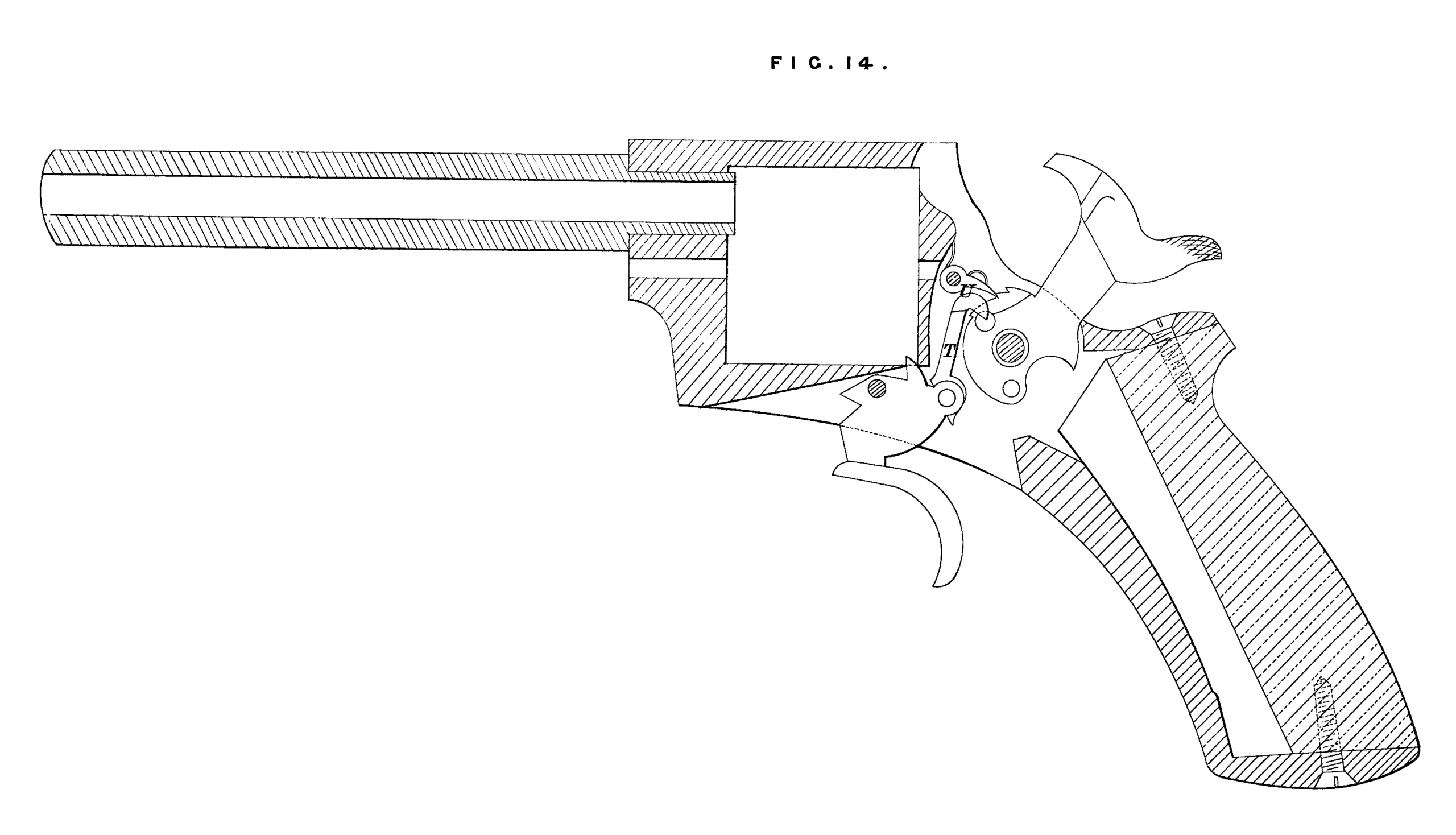
Fig. 14 represents a revolver pistol with my improved combination of lifting catch and sear adapted and applied thereto. T is the lifting catch with the hooked end acting in a slot, shewn by dotted lines, in the front of the hammer; U is the sear fixed at the top of the slot formed in the body and acted upon by a spring, as shewn. By means of this arrangement space is gained for forming the bents or notches in front of the hammer, thereby facilitating the adjustment of the acting parts. The hammer is enabled to be drawn further back owing to the form given to the stock, as represented in the Drawing.
Having thus described the nature of the said Invention, and in what manner the same is to be performed, I hereby declare that what I claim as of my Invention is,—
First, the adaptation and application to the kind of rifle guns referred to of an extractor of the several forms represented and described.
Secondly, the adaptation to the same kind of guns of a lever for throwing out cartridge cases, as represented and described.
Thirdly, the combination of an extractor and thrower acting together, as represented and described.
Fourthly, the adaptation and application to guns and pistols of a lever for fixing the barrels, as represented and described, also a lever acting in connection with the extractor, as described.
Fifthly, making the striking pin for sporting arms act in a curvilinear instead of a straight line.
And, lastly, the combination of a lifting catch , having a book on the end, with a sear placed at the top of the slot in the body, as represented and described.
In witness whereof, I, the said William Tranter, have hereunto set my hand and seal, the Fifteenth day of February, in the year of our Lord One thousand eight hundred and sixty-seven.
WILLIAM TRANTER. (L.S.)
Witness,
WILLIAM SPENCE,
8, Quality Court,
Chancery Lane,
Patent Agent.