
US 249649
Swing-out ejection
Be it known that I, Wm. Mason, of Hartford, in the county of Hartford and State of Connecticut, have invented new Improvements in Revolvers; and I do hereby declare the following, when taken in connection with the accompanying drawings and the letters of reference marked thereon, to be a full, clear, and exact description of the same, and which said drawings constitute part of this specification, and represent, in—
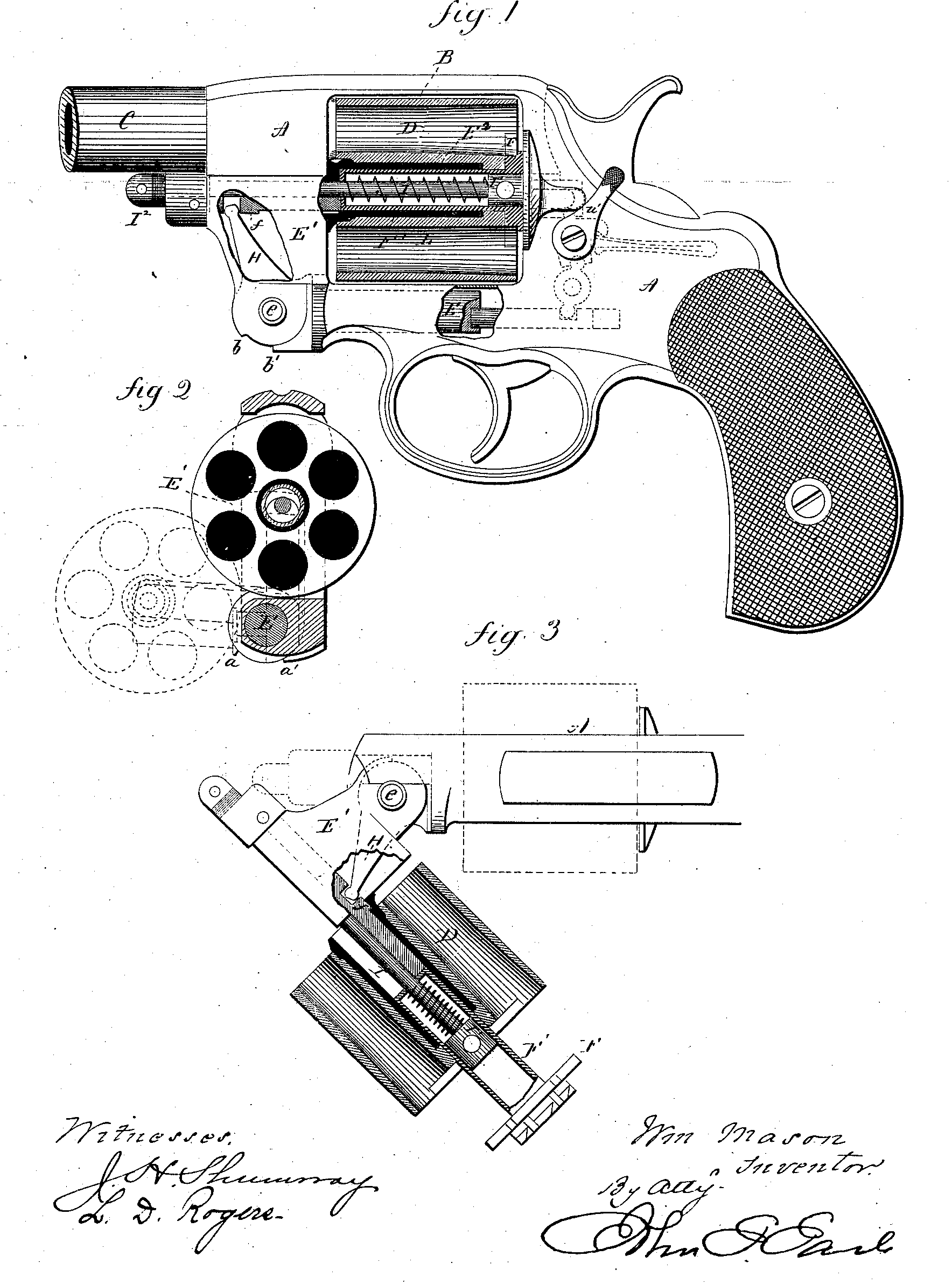
Figure 1, a sectional side view; Fig. 2, a transverse sectional view, showing the first or transverse swinging movement; Fig. 3, a top sectional view, showing the last or forward movement. .
This invention relates to an improvement in revolvers, with special reference to that class in which the cylinder is hung in its recess in the frame, so that it may be turned to one side sufficiently far to present the chambers of the cylinder outside the frame for the insertion or removal of the cartridges or shells, as the case may be, the object being to combine with the mechanism which permits such movement of the cylinder an ejecting device which will be operated by the swinging movement of the cylinder to eject the cartridge-shells, and so that the person holding the revolver may, by a quick twist of his hand, cause the cylinder to move out from its place in the frame, and when it has arrived at a point so far outside the cylinder that the heads of the shells are exposed the continued and completing outward or swinging movement of the cylinder will operate upon the ejector to force the shells from their respective chambers.
The invention consists in the arrangement-of a frame forward of the cylinder-opening, to swing outward upon a pivot or pivot-piece below the cylinder-opening, theaxis of said pivot substantially parallel with the axis of the cylinder and provided with a center-pin, on which the cylinder revolves, the said swinging part , of the frame hinged to the pivot, so that after the cylinder has, with the said swinging part, been swung outward in a plane at right angles to the frame until the cylinder is substantially free from its recess, it will then, turning on the
said hinge, swing forward in a plane parallel 50 with its axis, combined with an ejector operated during this latter or forward swinging movemeut to force the shells from their place in the cylinder.
A represents the frame, of substantially the 55 usual outline, with a recess, B, for the cylinder, and provided with the barrel C and the usual lock mechanism for successively presenting the chambers of the cylinder into line with the .barrel and discharging the cartridges presented 60 by such chambers in substantially the usual manner.
D is the cylinder, of substantially the usual form.
In the frame below the cylinder is a spindle 65 or pivot-piee’e, E, the axis of which is substantially parallel with the axis of the cylinder, but so that it may be rotated in its place in the frame, as hereinafter described. To the forward end of this pivot E a part, E’, of the frame is 70 hinged, as at e’. This part E’ fits into a corresponding recess made on the inside of the frame A forward of the cylinder-opening, as seen in Fig. 1, and in broken lines, Fig. 2. The said part E’ has the center-pin E2 attached to 75 or made a part of it, the axis of which, when in place, as seen in Fig. 1, is substantially parallel with the axis of the pivot E. On this center-pin the cylinder D is arranged so as to be rotated in the usual manner. Thus arranged, 80 the part E’ and the cylinder upon its center-pin may be turned from the frame, swinging on the pivot E as the center, and in a path at right angles to the frame or axis of the cylinder, until the cylinder is clear from the frame, 85 as seen in broken lines, Fig. 2. Then the part E’ of the cylinder may be turned forward on the hinge between the part E’ and the pivot E on a plane parallel with the axis of the center-pin, as seen in Fig. 3, which brings the cyl- 90 inder to a position, inclined to the frame, as shown in the said Fig. 3. Under this arrangement of the parts; if the person holding there-volver give it a quick twist to the right, it will cause the cylinder and the part E’ to quickly 95 swing out from the frame, as in Fig. 2, turning on the pivot E as its center until its movement in that direction is arrested by a shoulder, a, on the pivot part coming against a corresponding shoulder, a’, on the frame or stationary part, (or other suitable stop,) which occurs, as seen in Fig. 2, when the cylinder is free from frame. Then the force given to it by the twisting motion before mentioned will cause the cylinder and part E’ to turn forward upon the hinge e, as from the position in broken lines, Fig. 2, -to the position shown in solid lines, Fig. 3, until such forward ‘movement is arrested by a shoulder, b. on the swinging part striking a corresponding shoulder, b’, on the pivot part, or other suitable stop. A reverse twisting movement—that is, atwist to theleft— will return the cylinder to its place. I have said the twist is to the right for opening and’ left for closing; but it will be understood that the arm may be made for the cylinder to move in –the opposite direction, in which ca=e the twisting movement will be reversed.
The ejector is’of that character well known as-the “star ejector”—that is to say, a starshaped plate, F, arranged in a recess at the reay end of the cylinder, or so that parts of it will lie beneath the flange of the several cartridges when in place in the cylinder, and so that a reverse movement of the said plate, as‘ from-the position in Fig. 1 to that in Fig. 2, will force the several cartridges or shells simultaneously outward from their respective chambers. As here represented, the ejector-plate Fas attached to an ejector-rod, F’, arranged through the rear end of the cylintler and into the center-pin, the said center-pin made hollow or tubular to receive the said ejector-rod.
In the swinging pant E’ is a follower, / arranged longitudinally and soasto bearagainst the forward end of the ejector-rod, and so that the movement of thesaid followerrearward will Jorrespondingly move the ejector rearward, as rom-theposition in Fig. 1 to that in Fig. 3.
To automatically operate the ejector, an arm, a, 1s1 attached to or made a part of the pivot S; and lies in a recess in the swinging part E’ n a plane substantially parallel with the axis the ejector-rod and the follower/. This irm, being stationary upon the pivot, turns vith the pivot, and the swinging part in the irst movement, as from the position in Fig. 2 o that shown inbroken lines, same figure; but n the last or forward part of the swinging aovement the swinging part E*’ turns upon ts hinge independent of said arm, and so that he said arm H, remaining stationary, is rought from the position away from the cyl-oder in Fig. 1 to the position near the cylin-ev, as in Fig. 3. The upper end of the arm * l?.,n connection with the follower /, as seen a FigSi 1 and 3. Hence during the last or for-rard- swinging movement, the follower will emain stationary with the arm H, as will the jector, which will cause the swinging part nd cylinder to slide forward on the ejector-sd, as from the position in broken lines, Fig.
, to that seen in solid lines, same figure, and hicli produces practically the rear or ejecting
movement of the ejector-plate.- Hence by the twisting movement given to the arm, as before referred to, the ejector withdraws the shells from, the cylinder, and the reverse swinging movement, which returns thecylinderfirstfrom the position seen in Pig. 3, solid lines, to that seen in broken lines, same figure, will return the ejector to its place, and finally the cylinder and the parts thereto connected to their place of rest in the frame.
The follower may be connected directly to or made a part of the ejector-ro l; but I prefer to make the follower in a separate piece from the ejector, so that it will not rotate with or interfere with the rotation of the ejector-rod, which must turn with the cylinder.
In case the ejector-rod is extended so as to engage directly with the arm H, that engagement should be such as to permit the rotation , of the ejector-rod with the cylinder. This might be done by an annular groove around the center-pin, in which the upper end of the arm H would work. If the ejector-rod be made separate from the follower, then it is necessaryto < provide means to automatically return the ejector during the return of the swinging part. To do this I introduce through the ejector-rod a spindle, I, having a head, F, at its rear corresponding to the internal diameter of the hollow ejector-rod. This spindle is introduced through the ejector at the rear and made fast to the swinging part at the front by a nut, F, or otherwise. Around the spindle I, within the ejector-rod, is a spring, L, which bears against the head I' of the spindle at the rear, and at its forward end against a seat in the ejector-rod, so that as the ejector is thrown outward—or, which is the same thing, the cylinder forward—the spring is compressed between its seat in the rod and the head F of the spindle, as seen in Pig. 3. Hence, d the follower be not connected directly to the ejector-rod, the spring will serve to return the ejector, as the follower permits it to do in the closing movement of the swinging part. This arrangement of the hollow ejector-rod, spin die,and follower, as well as the mechanism shown in Pig. 1 for locking the swinging part in place, is the same as that shown in an application for Letters Patent which 1 have filed on even date herewith, designated as “ CaseB,” and requires no further description in this application than to say that a locking mechanism must be provided which will secure the cylinder and swinging part in place, and such locking mechanism should be such that the person holding tbe'pistol may, by his thumb or finger, disengage that locking mechanism, so as to be able to throw the cylinder outof and into place, as before described, without applying the hand directly thereto. The thumb piece or lever by which he is enabled to do this is shqwn at u' Fig.^1, and is the same as that shown in my application before referred to. ’ I claim— 1. In a revolver, the swinging part E',having the center-pin on which the cylinder revolves attached thereto or made a part of it and hinged to a pivot-piece in the frame below the cylinder-opening, the axis of said pivot-5 piece substantially parallel with the said center-pin, and so that the said swinging part, with the cylinder, will swing outward from its place in the frame, turning upon the saidpiv-ot-piece as its center of motion and in a plane io at right angles to the axis of the cylinder, and when the cylinder shall have passed from its recess in the frame it will then turn forward upon the hinge which connects it to said pivot-piece in a plane parallel with the axis of 15 said pivot-piece, combined with an ejector arranged through the center-pin for longitudinal movement, and mechanism substantially such as described, to engage said ejector during the forward swinging movement of the 20 cylinder and impart to the said ejector a rear movement, substantially as described. 2. In a revolver, the swinging part E', hav-iag the center-pin on which the cylinder revolves attached thereto or made a part of it 25 and hinged to a pivot-piece in the frame below the cylinder-opening, the axis of said pivot-niece substantially parallel with the said center-pin, and so that the said swinging part, with the cylinder, will swing outward from its 30 place in the frame, turning upon the said pivot-piece as its center of motion and in a plane at right angles to the axis of the cylinder, and when the cylinder shall have passed from its recess in the frame it will then turn forward 35 upon the hinge which connects it to said pivot-piece in a plane parallel with the axis of said pivot-piece, combined with an arm rigidly attached to the said pivot-piece, arranged 1 to turn with the cylinder in its first or outward j 40 swinging movement, but stationary in the last or forward swinging movement of the cylin- I tier, au ejector arranged through said cylinder for longitudinal movement, and a follower in the swinging part forward of said rod, with which said arm will engage to impart a rear movemen t to the said ejector during the last or forward swinging moveme'nt of the cylinder, substantially as described. 3. In a revolver, the swinging part E', having the center-pin on which the cylinder revolves attached thereto or made a part of it and hiuged to a pivot-piece in a frame below the cylinder-opening, the axis of said pivot-piece substantially parallel with the said center-pin, and so that the saidjswinging part, with the cylinder, will swing outward from its place in the frame, turning upon the said pivot-piece as its center of motion and in a plane at right angles to the axis of the cylinder, and when the cylinder shall have passed from its recess in the'frame it will then turn forward upon the hinge which connects it to said pivot-piece in a plane parallel with the axis of said pivot-piece, combined with au arm rigidly attached to the said pivot-piece, arranged to turn with the cylinder in its first or outward swinging movement, but station ary in the last or forward swinging movement of the cylinder, au ejector arranged through said cylinder for longitudinal movement, and a follower in the swinging part forward of said rod, with which said arm will engage to impart a rear movement to said ejector during the last or forward swinging movement of the cylinder, and a spring within the rod operating to draw the ejector to its place in the cylinder, substantially as described. WILLIAM MASON. Witnesses: Saml. Knous, Dwight A. Perkins,