
British 2961
Breech-loading Revolver Fire-arms.
LETTERS PATENT to John Adams, of Number 391, Strand, in the County of Middlesex, for the Invention of “ Improvements in the Construction of Breech-loading Revolver Fire-arms.”
Sealed the 17th April 1867, and dated the 22nd October 1867.
PROVISIONAL SPECIFICATION left by the said John Adams at the Office of the Commissioners of Patents, with his Petition, on the 22nd October 1867.
I, John Adams, of Number 391, Strand, in the County of Middlesex, do hereby declare the nature of the said Invention for “ Improvements in the Construction op Breech-loading Revolver Fire-arms,” to be as follows:—
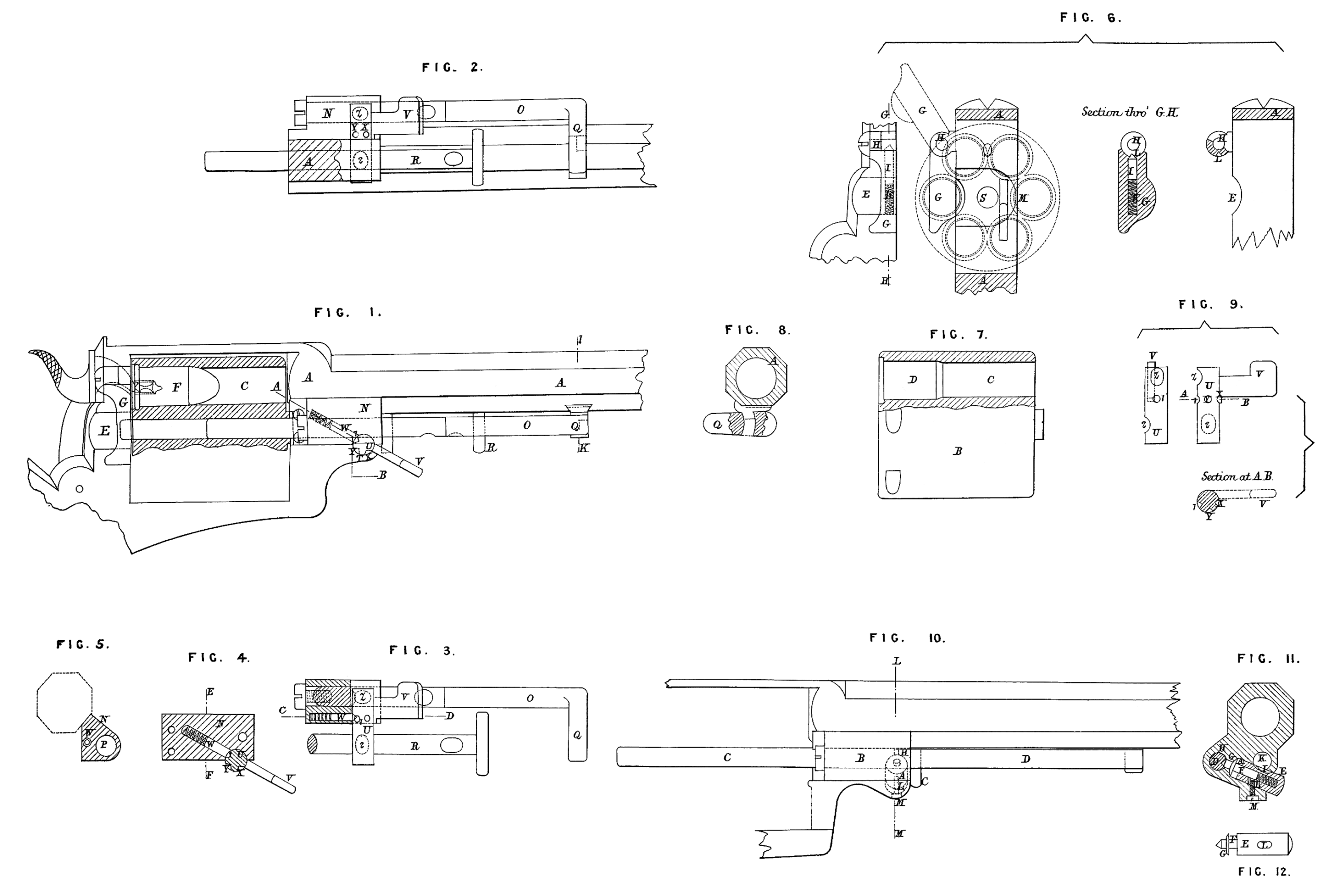
In constructing breech-loading revolver fire-arms in accordance with this Invention a frame and barrel as described in the Specification of my Invention for which Letters Patent were granted to me bearing date the Twenty-eighth day of July 1866, No. 1959, are used. A cylinder is introduced into the frame, the chambers of such cylinder being drilled through the same from end to end, and the back part of each chamber being made larger to the length of the cartridge than the front part .thereof ; this enlargement is parallel, and does not taper in any way excepting at the front end, so as to allow the ball to pass over freely into the smaller part of the chamber. On the side of the frame at the rear end of the cylinder a sufficient quantity of metal is cut away to allow the cartridges (which are of the description known as “central-fire” cartridges) to be inserted into each successive chamber as the cylinder is rotated. To prevent the cartridges from falling out through the opening thus cut away a small shield is attached to the frame by means of a hinged joint, which shield fits into the above-mentioned opening, and when closed prevents the cartridges from falling out. The shield when closed is kept in its position by means of a small bolt and a spiral spring which are inserted into a hole drilled through the shield. One end of the bolt is coned, and when the shield is closed is forced by the spiral spring into a small recess adapted to the shape of the coned end, which recess is cut into that portion of the hinged joint of the shield which is fixed to the frame. The shield is thus held in its position when down, and by pressing the shield upwards with the finger the coned end of the bolt slips out of the recess, and allows the shield to be turned up when it is desired to free the opening above described. The fixed shield ordinarily employed in revolver fire-arms is dispensed with, the chambers of the cylinder being protected when on the side of the frame opposite to that on which the moveable shield is placed by a portion thereof being covered by the frame, and the cartridges thus prevented from falling out. Attached to the frame of the barrel in front of the cylinder is a piece of metal which carries a moveable rod in a line with the opening in the frame above described. This rod is for the purpose of pushing out the cartridges before or the cartridge cases after the revolver has been fired ; this rod is called the ejector, and the hole through which it passes is called the ejector hole. The end of the ejector which is farthest from the cylinder is turned at a right angle, or nearly so, and when in its normal position lies under the barrel. The cylinder rod runs parallel with the ejector through a hole cut through the frame, and in order to keep both in their normal positions when the revolver is ready for firing a hole is drilled through a portion of the frame in front of the cylinder, the same cutting partially into the ejector and the cylinder rod, and also into the piece of metal which carries the ejector ; into this hole is inserted a bolt having for its object the locking both of the ejector and the cylinder rod when in their normal positions ; this bolt, which may be termed the “ primary ” bolt, is fitted to the hole, and has a thumb piece attached to it for the purpose of turning it round ; this thumb piece, when both the ejector and the cylinder rod are in their normal positions lies flat against the piece of metal which carries the ejector, it is kept in that position by means of a spiral spring or a bolt similar or analogous to that described above as being inserted into the moveable shield. This spring and bolt (which bolt may be termed the u secondary ” bolt) may either be inserted into the piece of metal which carries the ejector or into the frame itself, and the coned end thereof when the