
British 1959
LETTERS PATENT to John Adams, of No. 391, Strand, in the County of Middlesex, for the Invention of “ Improvements in the Construction op Revolver Fire-arms, and in Apparatus employed in their Manufacture, also in Cartridges to be used therewith.”
Sealed the 23rd November 1866, and dated the 28th July 1866.
PROVISIONAL SPECIFICATION left by the said John Adams at the Office of the Commissioners of Patents, with his Petition, on the 28th July 1866.
I, John Adams, of No. 391, Strand, in the County of Middlesex, do hereby declare the nature of the said Invention for “ Improvements in the Construction op Revolver Fire-arms, and in Apparatus employed in their Manufacture, also in Cartridges to be used therewith,” to be as follows:—
This Invention has for its object improvements in the construction of revolver fire-arms, and in apparatus employed in their manufacture, also in cartridges to be used therewith.
In constructing revolver fire-arms I take a forging of iron or steel which has been reduced roughly to the form of the barrel of the revolver pistol or fire-arm with the solid frame for the revolving cylinder, and I bore out the barrel from end to end, making also a small hole concentric with the bore in the back of the frame for the revolving cylinder. This forging may either originally have a space left in it for the revolving cylinder, or such a space may be subsequently cut out of it 5 I then place the forging between two centres in a holder, which is fixed to a slide rest; one of these centres fits into the bore, and the other into the aforesaid small hole concentric with the bore, and one of these centres travels by means of a screw thread parallel with the bore, in order to secure the forging firmly and accurately in its proper position. The forging is then advanced by means of the slide rest up to two revolving cutters between which the lower portion of the frame for the revolving cylinder passes, and is reduced to the proper dimensions so as to receive the breech piece herein-after described; I then transfer the forging to another holder which is fixed to a slide rest, where it is secured between similar centres to those above described. This holder is furnished at one end with a dividing plate, by means of which all the necessary angles to the barrel of the revolver are obtained with perfect accuracy. The forging is then advanced by means of the slide rest up to one revolving cutter, which in succession performs all the necessary outside cuts to the barrel. The manner in which the forging is held during these operations between centres, as above described, ensures perfect accuracy in the required thickness of the sides of the barrel, and also ensures that all the barrels shall be alike. I then lay the work on a metal holder with the barrel between two studs or blocks thereon, and I pass a spindle fitting the barrel accurately down the barrel and through corresponding holes in hardened steel bushes fitted into the studs or blocks. The work is in this way accurately set on the holder for two passages or holes to be bored underneath the barrel and truly parallel to the bore thereof; one of these holes is to receive the pin or axis of the revolving cylinder, and the other the plunger of the ramming apparatus. To ensure the required truth in the positions and directions of these holes there are other hardened steel bushes fitted in the aforesaid studs or blocks on the holder, and the drill is guided up to the work by the passages in these bushes with constant uniformity; then in order to complete the recess for the ramming apparatus, and recesses for the parts of the lock, the work is fixed on a holder between centres, as before described, and held in position by the bore and the small hole concentric with the bore. The holder is so made as to receive and hold in this manner between separate centres four different barrels or pieces, and it holds each in a suitable position to be presented to the tools, and these positions are different the one from the other. The several pieces thus held are advanced by means of a slide rest up to four revolving cutters, and so a cut of the required depth is made in each piece; then the slide rest is drawn back, and the pieces are shifted from one pair of centres to another of the holder, except that one piece which has been on all the centres and in which the slots are all made is removed from the machine, being so far finished, and another fresh piece is brought to the machine to supply its place. The slide rest is then again advanced to the cutters, and so the work goes on, each piece remaining in the machine until the necessary slots to admit the ramming apparatus and portions of the lock are cut to the exact required dimensions and form. Several operations are in this way performed at the same time in one machine, whereby a great saving of expense in the manufacture is secured together with great accuracy. The barrel and frame made as above described is not attached directly to the wooden stock or handle of the revolver, but to its rear end a connecting metal frame is attached by screws, and to this the stock is fixed. This connecting metal frame is the breech piece already mentioned ; it is accurately shaped by means of revolving cutters, and contains within it most of the parts of the lock.
The ramming apparatus consists of three parts, firstly, a cylindrical plupger fitting accurately the hole bored for it in the frame as already described ; secondly, a lever tying along under the barrel and at its rear end bent downwards so as to pass beneath the pin or axis of the chambers, and made to fit partly into the slot cut for it in the frame as before described, and partly into a corresponding slot cut in the plunger and head of the pin or axis of the chambers; and, thirdly, a link connecting the plunger and lever; this link is contained in the slot in the plunger. The lever turns on a pin passing through its rear end and also through the frame immediately above the hole or passage bored for the plunger. By arranging the ramming apparatus in this manner the whole is made, powerful and compact and the parts are fitted very readily. The lever rod is secured in position when not in use by means of a small bolt which is hollowed at one end about two-thirds of its length to contain a small spiral spring; this bolt is sunk into a hole at the end of the lever nearest the muzzle of the barrel to within a quarter of an inch of its entire length, and secured by means of a small screw; this bolt is acted upon by the spiral spring and works with a suitable catch attached to the barrel, thus firmly secures the rod while tying along underneath the barrel.
The percussioning of the cylinders or the cutting the recesses to receive the nipples is effected in the following manner :—When the chambers are bored out, a small hole concentric with each of them is bored through the back of the cylinder, this small hole afterwards receives the nipple. A suitable holder is provided and fixed to the bed of the machine, in the sides of which hardened steel bushes are fixed ; through these bushes a moveable hardened steel mandril or pin fitting the chamber, and the small hole concentric with it at the base passes. The cylinder is then by turning it on this steel mandril or pin which forms an axis to the cylinder brought up to a revolving cutter corresponding in size with the recess to be cut and placed at a distance from the aforesaid mandril or axis equal to the distance from centre to centre of the chamber; the cylinder is thus pressed up against the revolving cutter until a cut of the desired depth is made, when one cut is complete the cylinder is shifted round and the mandril or axis entered into another chamber and a second cut is made as before, and so on until completed.
I construct the ratchet at the back of the cylinder by means of which the cylinder is turned when in use in such a manner that a portion of it is left flat, and so as to come close to the back of the solid frame in which the cylinder is held; by this means a large bearing surface is provided to rest against the frame, so that the recoil may be firmly resisted. I construct a cylinder to use cartridges carrying their own fulminating priming to be loaded at the muzzle of the cylinder instead of as heretofore at the breech end thereof in order to secure the free revolution of the cylinder and to admit of the same ramming apparatus as above described being used for charging the chambers of the cylinder. Each chamber of this cylinder is bored parallel from the muzzle sufficiently deep to imbed the bullet; a small shoulder is then left, and a shallow’ recess or groove may be cut in the chamber just in advance of the shoulder, so that in ramming down the bullet against this shoulder its base may be forced into the small recess or groove. The bullet then becomes firmly held in position and offers sufficient resistance to the blow of the hammer to cause explosion. From this shoulder to the necessary depth of the chamber I bore out the chamber a little smaller than at the muzzle, and by preference slightly conical, so that when metal cartridge cases or cups which fit the bottom of the chamber are used they may after each discharge be easily pushed out of the chamber; this I do by means of a small bolt fixed to the frame at the breech end of the cylinder. This bolt may also be made available for fixing the cylinder when the revolver is not in use at the breech end of the chamber I bore a small hole completely through it concentric with the bore of the chamber, through which the nose of the hammer passes, and strikes the base of the cartridge, thereby causing ignition. Sometimes I employ cartridges with complete metal capsules or cases having a fulminating priming at their rear ends and very similar to breech-loading cartridges heretofore employed, but made conical so as to fit to the cone to
which the back of the chamber is bored as before described, I prefer, however, to make the cartridges only with a small metal capsule somewhat similar to an ordinary percussion cap; this forms the rear end of the cartridge and ensures a gas-tight joint when the cartridge is fired. The sides of the cartridge are made of skin or other material which will consume when the charge is fired. In this arrangement in order that the capsule may be firmly supported to receive the blow of the hammer, which is to explode the priming, I interpose a stem between the base of the bullet and the capsule, this stem is blown out on firing, leaving behind only the small metal capsule which is readily displaced and falls out.
SPECIFICATION in pursuance of the conditions of the Letters Patent, filed by the said John Adams in the Great Seal Patent Office on the 28th January 1867.
TO ALL TO WHOM THESE PRESENTS SHALL COME, I, John Adams, of No. 391, Strand, in the County of Middlesex, send greeting.
WHEREAS Her most Excellent Majesty Queen Victoria, by Her Letters Patent, bearing date the Twenty-eighth day of July, in the year of our Lord One thousand eight hundred and sixty-six, in the thirtieth year of Her reign, did, for Herself, Her heirs and successors, give and grant unto me, the said John Adams, Her special licence that I, the said John Adams, my executors, administrators, and assigns, or such others as I, the said John Adams, my executors, administrators, and assigns, should at any time agree with, and no others, from time to time and at all times thereafter during the term therein expressed, should and lawfully might make, use, exercise, and vend, within the United Kingdom of Great Britain and Ireland, the Channel Islands, and Isle of Man, an Invention for “ Improvements in the Construction o? ‘Revolver Fire-arms, and in Apparatus employed in their Manufacture, also nr Cartridges to be used therewith/* upon the condition (amongst others) that I, the said John Adams, my executors or administrators, by an instrument in writing under my, or their, or one of their hands and seals, should particularly describe and ascertain the nature of the said Invention, and in what manner the same was to be performed, and cause the same to be filed in the Great Seal Patent Office within six calendar months next and immediately after the date of the said Letters Patent.
NOW KNOW YE, that I, the said John Adams, do hereby declare the nature of the said Invention, and in what manner the same is to be performed, to be particularly described and ascertained in and by the following statement thereof, that is to say :—
This Invention has for its object improvements in the construction of revolver fire-arms, and in apparatus employed in their manufacture, also in cartridges to be used therewith.
In constructing revolver fire-arms I take a forging of iron or steel which has been reduced roughly to the form of the barrel of the revolver pistol or fire-arm with the solid frame for the revolving cylinder, and I bore out the barrel from end to end, making also a small hole concentric with the bore in the back of the frame for the revolving cylinder. This forging may either originally have a space left in it for the revolving cylinder, or such a space may be subsequently cut out of it; I then place the forging between two centres in a holder which is fixed to a slide rest; one of these centres fits into the bore, and the other into the aforesaid small hole concentric with the bore, and one of these centres travels by means of a screw thread parallel with the bore in order to secure the forging firmly and accurately in its proper position. The forging is then advanced by means of the slide rest up to two revolving cutters, between which the lower portion of the frame for the revolving cylinder passes and is reduced to the proper dimensions so as to receive the breech piece hereinafter described. I then transfer the forging to another holder which is fixed to a slide rest, where it is secured between similar centres to those above described. This holder is furnished at one end with a dividing plate, by means of which all the necessary angles to the barrel of the revolver are obtained with perfect accuracy. The forging is then advanced by means of the slide rest up to one revolving cutter, which in succession performs all the necessary outside cuts to the barrel. The manner in which the forging is held during these operations between centres, as above described, ensures perfect accuracy in the required thickness of the sides of the barrel, and also ensures that all the barrels shall be alike, I then lay the work on a metal holder with the barrel between two studs or blocks thereon, and I pass a spindle fitting the barrel accurately down the barrel and through corresponding holes in hardened steel bushes fitted into the studs or blocks. The work is in this way accurately set on the holder for two passages or holes to be bored underneath the barrel and truly parallel to the bore thereof. Oue of these holes is to receive the pin or axis of the revolving cyliuder, and the other the plunger of the ramming apparatus. To ensure the required truth in the positions and directions of these holes there are other hardened steel bushes fitted in the aforesaid studs or blocks on the holders, and the drill is guided up to the work by the passnges in these bushes with constant uniformity. Then in order to complete the recess for the ramming apparatus, and recesses for the parts of the lock, the work is fixed on a holder between centres as before described, and held in position by the bore and the small hole concentric with the bore. The holder is so made as to receive and hold in this manner between separate centres four different barrels or pieces, and it holds each in a suitable position to be presented to the tools, and these positions are different the one from the other. The several pieces thus held are advanced by means of a slide rest up to four revolving cutters, and so a cut of the required depth is made in each piece, then the slide rest is drawn back and the pieces are shifted from one pair of centres to another of the holder, except that one piece which has been on all the centres and in which the slots are all made is removed from the machine, being so far finished, and another fresh piece is brought to the machine to supply its place ; the slide rest is then again advanced to the cutters, and so the work goes on, each piece remaining in the machine until the necessary slots to admit the ramming apparatus and portions of the lock are cut to the exact required dimensions and form. Several operations are in this way performed at the same time in one machine, whereby a great saving of expense in the manufacture is secured, together with great accuracy. The barrel and frame made as above described is not attached directly to the wooden stock or handle of the revolver, but to its rear end a connecting metal frame is attached by screws, and to this the stock is fixed. This connecting metal frame is the breech piece already mentioned. It is accurately shaped by means of revolving cutters, and contains within it most of the parts of the lock.
The ramming apparatus consists of three parts; firstly, a cylindrical plunger fitting accurately the hole bored for it in the frame, as already described ; secondly, a lever lying along under the barrel, and at its rear end bent downwards so as to pass beneath the pin or axis of the chambers and made to fit partly into the slot cut for it in the frame as before described, and partly into a corresponding slot cut in the plunger and head of the pin or axis of the chambers ; and, thirdly, a link connecting the plunger and lever; this link is contained in the slot in the plunger. The lever turns on a pin passing through its rear end and also through the frame immediately above the hole or passage bored for the plunger. By arranging the ramming apparatus in this manner the whole is made powerful and compact, and the parts are fitted very readily. The lever rod is secured in position when not in use by means of a small bolt which is hollowed at one end about two-thirds of its length to contain a small spiral spring. This bolt is sunk into a hole at the end of the lever nearest the muzzle of the barrel to within about a quarter of an inch of its entire length, and secured by means of a small screw. This bolt is acted upon by the spiral spring, and works with a suitable catch attached to the barrel, this firmly secures the rod when lying along underneath the barrel. The per-cussioning of the cylinders or the cutting the recesses to receive the nipples is effected in the following manner:—When the chambers are bored out a small hole concentric with each of them is bored through the back of the cylinder; this small hole afterwards receives the nipple. A suitable holder is provided and fixed to the bed of the machine, in the sides of which holder hardened steel bushes are fixed ; through these bushes a moveable hardened steel mandril or pin fitting the chamber and the small hole concentric with it at the base passes; the cylinder is then by turning it on this steel mandril or pin which forms an axis to the cylinder brought up to a revolving cutter corresponding in size with the recess to be cut, and placed at a distance from the aforesaid mandril or axis equal to the distance from centre to centre of the chamber. The cylinder is thus pressed up against the revolving cutter until a cut of the desired depth is made. When one cut is completed the cylinder is shifted round and the mandril or axis entered into another chamber, and a second cut is made as before, and so on until completed.
I construct a cylinder to use cartridges carrying their own fulminating priming to be loaded at the muzzle of the cylinder instead of as heretofore usual at the breech end thereof, in order to secure the free revolution of the cylinder and to admit of the same ramming apparatus as above described being used for charging the chambers of the cylinder. Each chamber of this cylinder is bored parallel from the muzzle sufficiently deep to embed the bullet. A small shoulder is then left and a shallow recess or groove may be cut in the chamber just in advance of the shoulder, so that in ramming down the bullet against this shoulder its base may be forced into the small recess or groove ; the bullet then becomes firmly held in position and offers sufficient resistance to the blow of the hammer to cause explosion. From this shoulder to the necessary depth of the chamber I bore out the chamber a little smaller than at the muzzle, and by preference slightly conical, so that when metal cartridge cases or cups which fit the bottom of the chamber are used they may after each discharge be easily pushed out of the chamber. This I do by means of a small bolt fixed to the frame at the breech end of the cylinder. This bolt may also be made available for fixing the cylinder when the revolver is not in use. At the breech end of the chamber I bore a small hole completely through it concentric with the bore of the chamber through which the nose of the hammer passes and strikes the base of the cartridge, thereby causing ignition. Sometimes I employ cartridges with complete metal capsules or cases having a fulminating priming at their rear ends, and very similar to breech-loading cartridges heretofore employed, but made conical so as to fit to the cone to which the back of the chamber is bored, as before described.
I prefer, however, to make the cartridges only with a small metal capsule, somewhat similar to an ordinary percussion cap ; this forms the rear end of the cartridge and ensures a gas-tight joint when the cartridge is fired. The sides of the cartridge are made of skin or other material which will consume when the charge is fired. In this arrangement in order that the capsule may be firmly supported to receive the blow of the hammer which is to explode the priming I interpose a stem between the base of the bullet and the capsule, this stem is blown out on firing, leaving behind only the small metal capsule, which is readily displaced and falls out.
In order that my Invention may be fully understood and readily carried into effect I will proceed to describe the Drawings hereunto annexed.
Description of the Dbawinqs.
On Sheets 1, 2, and 3 of the Drawings are shown the various machines for reducing to the proper dimensions the rough forging of the barrel and frame. The barrel and frame are, as above stated, roughly forged to shape, and then the space for the revolving cylinder is cut out by boring numerous small holed around the edge of the part of the forging to be removed and punching out this part; or the part may be cut out by circular cutters or otherwise. Afterwards the barrel is bored from end to end, and a small hole is bored through the back of the frame concentric with the bore; this I prefer to do by boring the hole with a small drill carried at the end of a stem or mandril that is passed down and that fits the barrel. The lower portion of the frame is then reduced to its proper dimensions by being caused to pass between two circular cutters. A machine for effecting this is shown on Sheet 1 of the Drawings.
Figure 1 is a front view, Figure 2 a side view, and Figure 3 a plan of the machine.
a, a, are the two circular cutters which are carried on the end of an axis b, on which is a toothed wheel bl gearing with a pinion c1 on an axis c; on this axis are fast and loose pullies c2 for receiving a driving band or strap, and in this manner rotary motion is given to the axis b of the cutters. The axes b and c are carried by a headstock d, which is fixed to a bed similar to the bed of a lathe; this bed is not shown in the Drawing. The forging to be acted on by the cutters is held in the position shown by the Drawing between two points e, e1, of a holder carried by a slide / working on guides carried by a plate g> which is fixed to the bed in a similar manner to the headstock. One of the points e is fixed to a projection fl on the top of the slide, and the other point is formed on the end of a screw that screws into another projection /* on the slide. There is also a third point carried by the projection /1; this point is for entering a hole in the back of the frame, and prevents the forging from turning round upon the points a, €*. When the forging has been secured between the points the slide / is moved forward by turning the crank handle on the axis of the screw h, or it might be by self-acting gear, so as to pass the under side of the frame end of the forging between the two circular cutters a9 a. Between the cutters a, a, is a third cutter a1 which reduces the frame of the forging at the point & to its proper dimensions.
After the forging has been subjected to the action of the machine above described it is acted on by the machine shown on Sheet 2 of the Drawings in order to reduce the exterior of the barrel and frame to the required shape. Figure 1 is a front view, Figure 2 a side view, and Figure 3 a plan of the machine. In this machine the barrel is fixed between points of a holder carried by a slide rest similar to the one in the machine shown on Sheet 1. One of these points e is a fixed point; the other point e1 is capable of being moved backwards or forwards in a manner similar to the back centre of a lathe by turning the hand wheel t. Carried by the point d is a dividing plate k which can turn freely around the point; this plate carries a clamp k\ in which the frame portion of the rough forging is held so that the forging shall turn with the plate. In the plate are formed as many holes as it is desired that the exterior of the barrel should have sides; into either of these holes a spring catch enters to fix the plate whilst one of the sides of the barrel is being reduced to form. When one of the rough forgings has been fixed to the holder on the slide rest / in the manner above described the rest is moved forward to carry the exterior of the barrel or forging against the circular cutter l. After one side of the barrel has thus been reduced to shape the other sides are in succession reduced in a similar manner. At the same time that the sides of a barrel or forging are thus being reduced to form the rear end of the frame portion of another barrel or forging can be reduced by fixing it between a fixed joint m and a moveable point m1 carried by the same slide rest /, the barrel or forging being further held by a clamp n9 as shown at Figures 2 and 3.
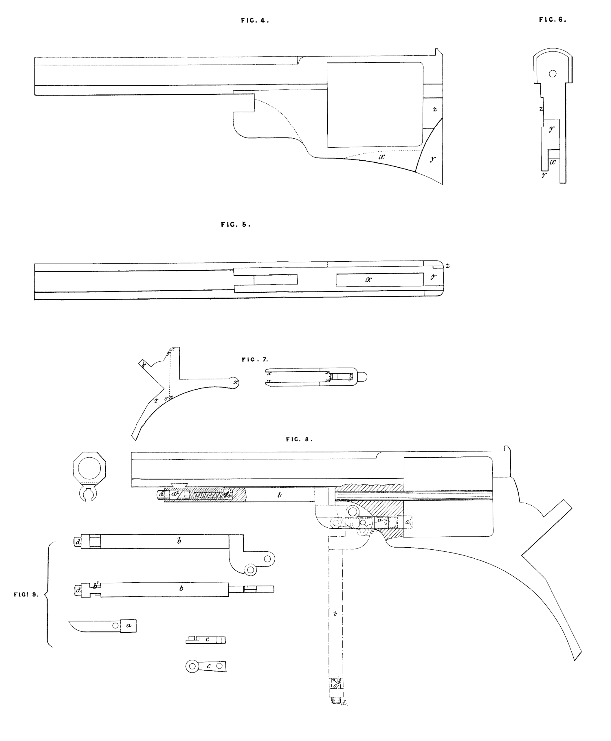
After that the barrel or forging has been operated on by this machine it is laid on the metal holder shown at Figures 4, 5, 6, 7, and 8 (Sheet 2). Figure 4 is a plan view of the holder shewing a barrel or forging held upon it; Figure 5 is a side view, Figure 6 an end view, and Figures 7 and 8 are transverse sections of the same. In this holder the ends of the barrel are held between the two end blocks o9 o\ Another block o2 passes up through the opening in the frame that is to receive the revolving cylinder, and the barrel is secured by a pin which fits the bore of the barrel, passing through a hole in the block o1, then through the barrel and into a hole in the block o2. The holes in the blocks may be fitted with hardened bushes if desired. When the barrel and frame has thus been secured two holes are bored in the frame, one to receive the axis of the revolving cylinder, and the other to receive the plunger of the ramming apparatus. The stems of the drills or cutters which are to form these holes are passed through holes formed in the block o\ and also through concentric holes in a block o3, and by this means the position of the holes bored in the frame is secured with the necessary accuracy. It is preferred that the holes in the block o8 should be bushed as shown in the transverse section Figure 7. A hole is bored in the block o* concentric with the holes in the blocks ol and o8 through which the drill or cutter is passed that is to bore the hole to receive the axis of the revolving cylinder in order that the drill or cutter may pass through the hole in this block to bore a continuation of the hole into the back of the frame.
When the holes have been bored in the frame as above described it is removed to be acted on by the machine shown at Sheet 3 of the Drawings. Figure 1 is a front view, Figure 2 a side view, and Figure 3 a plan of the machine. The axis of the revolving cutters of this machine is carried in the same manner as in the machine shown on Sheet 1; the slide rest to which the barrels or frames to be operated on are fixed also slides on guides similar to those shown on the same Sheet. The slide rest of this machine is arranged to carry a holder, to which are affixed four barrels to be acted on simultaneously by the circular cutters. One barrel and frame held between the centres a, a\ and a supporting point and thumbscrew o2 is acted on by the cutter No. 1 in order to complete the groove for the ramming apparatus. Another barrel held between the centres 5, h\ and supporting point and thumbscrew fc2 is acted on by the cutter No. 2 to form the groove x to receive the trigger and trigger spring. Another barrel held between centres c, c1, and by a clamp c2 is acted on by the cutter No. 3 to form a groove or recess y to receive a portion of the lock, and a fourth barrel held between centres d, d1, and by a clamp d2 is acted on by a cutter No. 4 to form the recess z, through which passes the point of the driver for giving a partial rotation to the cylinder. Four separate barrels are thus simultaneously acted on, and each barrel is in turn acted on by all the cutters. A full size view of the barrel and frame after it has been shaped by the cutters as above described is shown at Figures 4, 5, and 6 on Sheet 3.
On Sheet 4 of the Drawings is shown a machine for shaping the metal frame or breech piece by which the barrel is connected to the stock ; this machine is arranged to perform three different operations simultaneously on three different rough breech pieces.
Figure 1 is a front view; Figure 2 a side view, and Figure 3 a plan of the machine, the machine like those already described is composed of an axis carrying circular cutters, and of a slide rest and holder that carries the work. One rough breech piece is held by a clamp a in the position indicated by the diagram, Figure 4, in order that it may be acted on by the cutter No. 1, to accurately surface a portion of the tang and the rear end of the rough breech piece where it is connected “with the wooden stock or handle. This rough breech piece is transferred to and is held by the clamp b in the position shown by the diagram, Figure 5, in order that it may be acted on by the cutter No. 2 to form the slot x (see Figures 7), and a third breech piece is held by a clamp c in the position shown by Figure 6 to be acted on by a cutter No. 3 which cuts out the slot y. When each of the pieces has been in succession subjected to the action of all the three cutters it is ready to be attached to one of the barrel pieces made as already described. I would here remark that other parts or surfaces of the barrel and of the frame or breech piece may be similarly shaped by circular cutters, the barrel or breech piece separately or together being fixed to a slide rest as above described, by which it is moved up to the cutter, and the form of the barrel or breech piece being suitably designed to allow of such parts being shaped by circular cutters.
On Sheet 4 is also shown my arrangement of ramming apparatus for ramming the cartridges into the chambers of the revolving cylinder. At Figure 8 is shown a side view, partly in section, of the ramming apparatus, and Figures 9 show separately the parts of the ramming apparatus composed as above stated of three parts ; firstly, a plunger a fitting the hole bored for it in the frame; secondly, of the lever b bent downwards at its rear end to pass beneath the pin or axis of the chambers, and fitting partly in the slot cut for it in the frame and partly in a slot in the head of the pin or axis of the revolving chambers ; the third part of the ramming apparatus is a link c, which connects the lever b and plunger a, the manner of forming and jointing together the several parts is clearly shown in the Drawings, The catch for securing the lever b when the ramming apparatus is out of use is also clearly shown in Figure 8. d is the small hollow bolt of the catch containing the spiral spring d1, which presses the bolt outwards from the end of the lever; the bolt is stopped from moving out too far by a screw pin not shown in the Drawing ; the lever b near its outer end is cut away, as shown at b\ b\ on two opposite sides, the narrow portion left of the lever at this point is, when the lever is out of use, received between two clips formed as shown by the Drawing. A portion of the bolt d is cut away in a similar manner to the lever so that it may pass between the clipping pieces on the under side of the barrel. In order to bring this part of the bolt opposite the clips so that it may pass between them the bolt has to be pressed inwards, when the lever is to be secured by the clips, the bolt is pressed inwards merely by turning up the lever, the incline d2 on the bolt then strikes against the under side of the clips, and thus the bolt is pressed back, and as soon as the bolt has passed between the clips the bolt is again pressed forward by its spiral spring, the round portion of the bolt is then unable to pass between the clips, and the lever is held fast. When it is desired to release the lever from the catch the bolt is pressed inwards by the finger and the lever then turned down.
. On Sheet 5 of the Drawings is shown the arrangement of machinery for percussioning the ends of the revolving cylinders or shaping them to receive the nipples, a hole is first bored through the centre of the cylinder for the pin or axis on which it is to turn, and after the cylinder has been reduced to its proper dimensions the chambers of the revolving cylinder are then bored. To bore* the chambers in the cylinder I by preference first bore a small hole through or partly through one end of the cylinder and employ for this purpose a frame such as is shown in the section, Figure 1, in which to hold the cylinder whilst it is being bored, and the cutting tool or drill to form this hole is passed through the bushed hole b in the end of the frame. A pin a accurately fitting this hole, and the bushed hole b in the frame, is then inserted to hold the cylinder accurately in position in the frame, whilst a second hole is bored through another bushed hole 61 in the opposite end of the frame. The cylinder is then removed from this frame, and is held by a centre bolt between two plates c and d, as shown in Figure 2; each of these plates has formed through it as many bushed holes as it is desired that the cylinder shall have chambers, and two pins e,f, are passed through two of these holes into the two holes already bored in the opposite ends of the cylinder, the remainder of the holes are then bored in the cylinder, the bushed holes in the plates forming guides for the boring tools and ensuring the holes being correctly bored in the cylinder. The cylinder is then removed from between the plates and the chambers are bored to the proper dimensions for receiving the charge. The cylinder is hen acted on by the machine shown at Figures 3 and 4; this machine is for shaping the end of the cylinder to receive the nipples, a is a circular revolving cutter carried as in the machine shown on Sheet 1, the cylinder to be acted on by this cutter is held on a pin or mandril b, carried by a holder c, which is fixed to the same bed as that to which the frame carrying the axis of the revolving cutter is affixed; the pin or mandril b can be slid into or out of holes in the sides of the holder c, and thus the cylinder can readily be placed upon it; a portion of the pin on to which the cylinder is placed is made to fit one of the chambers of the cylinder, and also to pass through the small hole concentric with it, which is formed through the base of the cylinder; when the cylinder is thus held on the pin 6 a workman by hand urns the cylinder on the pin (or it may be turned by self-acting gear) and presses it against the cutter until the cutter has entered to the depth desired, if desired the depth to which the cutter is allowed to act may be regulated by a suitable stop, the cylinder is then removed from the pin and the pin is passed through a fresh hole in the cylinder and the same operation is repeated until all the recesses to receive the nipples are formed, I have not thought it necessary to give any further description of my improvements in revolving fire-arms with which such cartridges are to be used as they will be readily be understood from the description above given.
In witness whereof, I, the said John Adams, have hereunto set my hsa xxd and seal, this Twenty-fifth day of January, in the year of our Lord One thousand eight hundred and sixty-seven.
JOHN ADAMS. (l.s.>