
British 2263
LETTERS PATENT to William Edward Newton, of the Office for Patents, 66, Chancery Lane, in the County of Middlesex, Civil Engineer, for the Invention of “ Improvements in Revolving Fire-arms.”—A communication from abroad by Messrs. Perrin and Delmas, of Paris, in the Empire of France.
Sealed the 11th January 1860, and dated the 5th October 1859.
PROVISIONAL SPECIFICATION left by the said William Edward Newton at the Office of the Commissioners of Patents, with his Petition, on the 5th October 1859.
I, William Edward Newton, of the Office for Patents, 66, Chancery Lane, in the County of Middlesex, Civil Engineer, do hereby declare the nature of the said Invention for “ Improvements nr Revolving Fire-arms,” to be as follows:—
This Invention of improvements in revolving fire-arms is intended to be applied more particularly to pistols, and presents the following principal advantages, namely, first, great simplicity of parts; second, solidity, and the simultaneous action of all the parts, the result of which is that in drawing the trigger, the hammer or dog is cocked, then falls upon, strikes and explodes the cap, and then by a renewed pressure on the trigger, the same effects and movements take place with another charge of the breech, which is at the same time caused to rotate a certain part of a evolution, and so the motions are continuously repeated $ third, the ability to load the revolver without being obliged to dismount the breech, and also being able to ascertain by simply looking at the back end of the breech, how many shots have been discharged, and how many chambers remain loaded. In connexion with this improved arm cartridges and caps of peculiar construction are employed. The mechanism of the arm consists simply of a detent which carries the trigger, and which takes hold of and operates upon a rod attached to the end of a hammer, .thereby forming a compound lever. A link connects this rod with a spring fixed in the handle of the arm. By simply pressing on the trigger with the finger, the detent turns on its stud, and draws forward the rod at the lower end of the hammer, which is thereby drawn back, and the arm is cocked. When the detent is at the end of its course, it releases the rod of the dog or hammer, and the spring will then bring down the hammer with force on the cap, and explode the charge; after the discharge of the arm, the detent reassumes its primitive position by the effect of the rod, which rests upon the detent a little in advance of its centre. All the moving parts are thus by the action of the spring brought back to their normal position, or to a state of rest, until a new application of pressure acts upon and draws back the trigger. To the end of the detent is jointed a lever provided with a click whereby the breech piece is rotated when the detent is pulled back. The rotating breech is mounted on a moveable pin, which will admit of it being moved when required to be loaded or charged ; the rotating breech is also supported from behind by a strong fixed piece or breech through which a hole is made opposite the barrel, so that the hammer may strike exactly against the centre of the cap or cartridge. The cartridge or piece, which serves to receive the percussion or detonating cap consists of a copper tube prepared to receive a disc pierced in the centre. This tube is provided with a sort of anvil or nipple upon which the cap is placed. The disc and anvil or nipple are placed in the tube, and form a kind of wad or support against the blow of the hammer. This contrivance may be so modified as to admit of the tube serving a second time when provided with a new percussion cap.
SPECIFICATION in pursuance of the conditions of the Letters Patent filed by the said William Edward Newton in the Great Seal Patent Office on the 4th April 1860.
TO ALL TO WHOM THESE PRESENTS SHALL COME, I, William
Edward Newton, of the Office for Patents, 66, Chancery Lane, in the County of Middlesex, Civil Engineer, send greeting.
WHEREAS Her most Excellent Majesty Queen Victoria, by Her Letters Patent, bearing date the Fifth day of October, in the year of our Lord One thousand eight hundred and fifty-nine, in the twenty-third year of Her reign, did, for Herself, Her heirs and successors, give and grant unto me, the said William Edward Newton, Her special license that I, the said William Edward Newton, my executors, administrators, and assigns, or such others as I, the said William Edward Newton, my executors, administrators, and assigns, should at any time agree with, and no others, from time to time and at all times thereafter during the term therein expressed, should and lawfully might make, use, exercise, and vend, within the United Kingdom of Great Britain and Ireland, the Channel Islands, and Isle of Man, an Invention for “Improvements in Revolving Fire-arms,” being a communication from abroad by Messrs. Perrin and Delmas, of Paris, in the Empire of France, upon the condition (amongst others) that I, the said William Edward Newton, by an instrument in writing under my hand and seal, should particularly describe and ascertain the nature of the said Invention, and in what manner the same was to be performed, and cause the same to be filed in the Great Seal Patent Office within six calendar months next and immediately after the date of the said Letters Patent.
NOW KNOW YE, that I, the said William Edward Newton, do hereby declare the nature of the said Invention, and in what manner the same is to be performed, to be particularly described and ascertained in and by the following statement, reference being had to the Drawing hereunto annexed, and to the letters and figures marked thereon (that is to say) :—
This Invention of improvements in revolving fire-arms is intended to be applied more particularly to pistols, and presents the following principal advantages, namely,—1st, great simplicity of parts; 2nd, solidity, and the simultaneous action of all the parts, the result of which is that in drawing the trigger the hammer or dog is cocked, then falls upon, strikes, and explodes the cap, and then, by a renewed pressure on the trigger, the same effects and movements take place with another charge of the breech, which is at the same time caused to rotate a certain part of a revolution, and so the motions are continuously repeated; 3rd, the ability to load the revolver without being obliged to dismount the breech, and also being able to ascertain by simply looking at the back end of the breech how many shots have been discharged, and how many chambers remain loaded. In connexion with this improved arm cartridges and caps of peculiar construction are employed. The mechanism of the arm consists simply of a detent, which carries the trigger, and which takes hold of and operates upon a rod attached to the end of a hammer, thereby forming a compound lever. A link connects this rod with a spring1 fixed in the handle of the arm. By simply pressing on the trigger with the finger, the detent turns on its stud and draws forward the rod at the lower end of the hammer, which is thereby drawn back, and the arm is cocked. When the detent is at the end of its course, it releases the rod of the dog or hammer, and the spring will then bring down the hammer with force on the cap, and explode the charge. After the discharge of the arm the detent is caused to resume its primitive position by the effect of the rod, which rests upon the detent a little in advance of its centre. All the moving parts are thus, by the action of the spring, brought back to their normal position or to a state of rest until a new application of pressure acts upon and draws back the trigger a second time. To the end of the detent is jointed a lever, provided with a click, whereby the breech piece is rotated when the trigger and detent is pulled back. The rotating breech is mounted on a moveable pin, which will admit of it being moved when required to be loaded or charged. The rotating breech is also supported from behind by a strong fixed piece or breech, through which a hole is made opposite the barrel, so that the hammer may strike exactly against the centre of the cap or cartridge. The cartridge or piece which serves to receive the percussion or detonating cap consists of a copper tube, prepared to receive a disc pierced in the centre; this tube is provided with a sort of anvil or nipple, upon which the cap is placed. The disc and anvil or nipple are placed in the tube, and form a kind of wad or support against the blow of the hammer. This contrivance may be so modified as to admit of the tube serving a second time when provided with a new percussion cap.
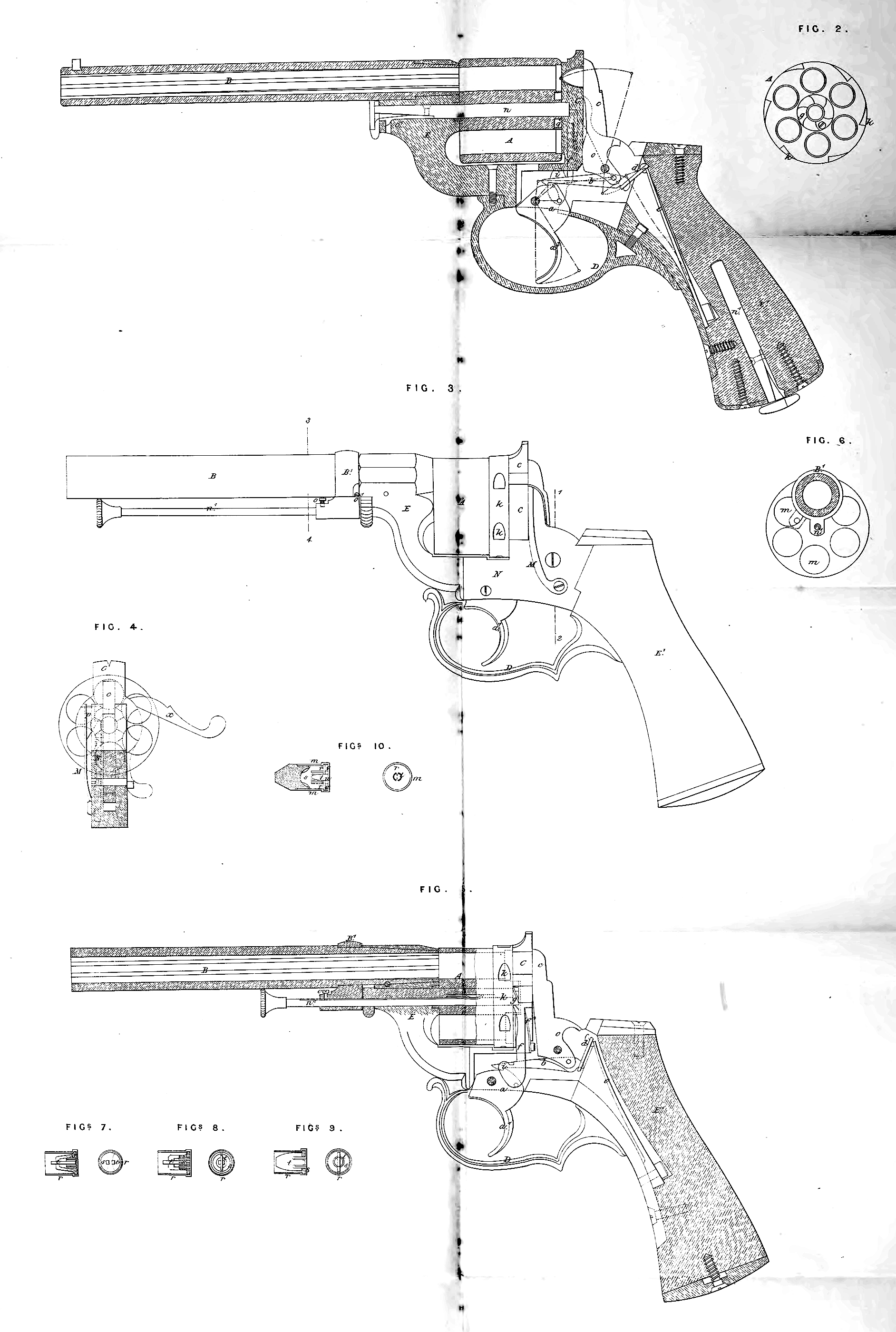
In the accompanying Drawing, Fig. 1 is a longitudinal vertical section of the improved revolver, the lock plate being removed the better to show the internal mechanism; Fig. 2 is a front view of the rotating breech detached; Fig. 3 is a side view of the revolver, shewing a special arrangement of ramrod for unloading the breech chambers; Fig. 4 is a transverse section of the arm, taken in the line 1, 2, of Fig. 3; Fig. 5 is a longitudinal vertical section of
Fig. 3.; Fig. 6 is a section taken in the line 3, 4, of Fig. 3; Figs. 7, 8, 9,
and 10 represent four arrangements of cartridges and caps to be adapted to the improved revolver. It will be seen that the mechanism is composed of a detent a, carrying the trigger a\ and a detent lever b, which takes into a notch in the detent. The hammer c forms with the detent lever a kind of compound lever. A link d is jointed to the binder extremity of the detent lever b,
and thus connects it with the spring e, which is fastened into the handle by a screw; this completes the nuipber of parts forming the lock movement.
On pressing upon the trigger a1 with the finger, the detent a will turn on its axis, and carry forward the rod 5, thereby drawing back and cocking the hammer. When the trigger detent b has reached the end of its course, it will present a convex surface to the detent lever a, and will thereby throw it up out of the nick in the detent, which will release the spring, and cause it to act on and depress the hammer on to the centre of the cartridge. After the hammer has struck the end of the cartridge, the detent will be caused to resume its former position by the lever b bearing upon it beyond its centre of motion. All the parts will by this means be suddenly brought by the spring e into their primitive position or state of rest until the trigger a1 be again acted upon. The detent a will therefore act upon the hammer c whenever pressure is exerted upon the trigger, by which means the continuous movement above mentioned will be produced. At the hinder part of the trigger detent a is a hinged lever /, the upper extremity of which acts as a click upon a ratchet wheel or set of projecting teeth g near the centre of the revolving breech, the number of teeth or projections corresponding in number to the number of chambers in the breech. It will be seen that at each movement of the mechanism the lever or click/in rising comes in contact with one of the ratchet teeth g, which it will push forward one tooth, and thereby bring a fresh chamber opposite the hammer. In order to ensure the taking of the click into the teeth of the ratchet g, the click is pressed forward into contact with them by a flat spring/*, Fig. 5, at its hinder part; thus the same pressure which acts upon the detent will cause the breech A to rotate at the same time that it sets the working parts in action. In order to ensure the exact position of each of the openings or chambers of the breech A opposite the barrel B, the same piece or click / forms at its lower part a sort of second arm i, which at the moment of its ascent, that is to say, when the detent is at the end of its course, takes into one of the nicks Jc made for that purpose in the circumference of the breech, and corresponding to the chambers of the revolver. The breech A will therefore, by means of the click/and its piece i, be firmly held during the fall of the hammer upon the cap. The breech, which may be removed by withdrawing the axis or shaft n, Fig. 1, from the part E, has its rotary motion, when loose, at first somewhat moderated by the action of a flat spring on the said shaft, and which occasions friction inside. For the purpose of dismounting the breech it is only necessary to press upon a second spring, carried by the axis n, which will disengage it from the fixed gudgeon o\ The principal fixed piece C, Fig. 1, forming the breech plate is perforated opposite the barrel B, and is countersunk behind in order to admit the head the hammer, which strikes through it in order to produce the explosion.
This arrangement allows of the hammer striking directly upon the cartridge without any intermediate parts. The circumference of the breech plate C which receives the recoil after percussion, is arranged in such a manner as to allow of the cartridges being seen, and consequently of seeing what chambers are loaded, the barrel B only being hidden. By this arrangement the friction of the rotating breech against this fixed surface will be diminished, and accidents will thereby be avoided, as it will be easy to see whether the weapon be loaded or not. An opening is made at the side of the piece C in order to facilitate the introduction of the cartridges into the chambers; when the loading has been effected, this opening is closed by a moveable piece. The trigger guard D is formed in such a manner as to serve as a support to the hand, in order to allow of the detent acting freely, and to enable the finger to act without altering the position of the hand.
In order to charge and ram down the different chambers of the revolver when cartridges are not employed ready prepared, and also to extract those cartridges which have exploded, a ramrod ft1 is employed, which is fixed in the butt E in the same manner as the axle n. To facilitate the operation of loading as much as possible, the pistol is provided with an additional piece M, which acts as a spring, and is screwed to the lock frame N (see Figs. 3 and 4). This rod carries a head with an inclined plane p, which bears against and raises at its lower part the lever / (which effects and regulates the rotation of the breech A) whenever the trigger is pulled, in order to bring its detent into action. This head p takes into a recess made for that purpose in that part of the lock plate N, which allows, by reason of the elasticity of the rod M, of its coming between the breech plate C and the hammer c, when, on slight pressure being applied to the trigger, this latter is slightly raised. In this raised position of the hammer the rotating breech is free to turn from left to right, and may be loaded with the greatest facility, when the rocking piece x has been brought into the position represented at Fig. 4. When, however, the detent a is put in action, the lever / having arrived at the top of its course will strike against the head p, and keep it away from the hammer during the effect of detonation and percussion.
A second arrangement for unloading is represented in Figs. 3 to 6. The forward part of the barrel B is embraced by a moveable socket B1, which carries a ramrod n\ This ramrod has in part of its length a groove into which takes a fixed stud o, by which it is prevented from entirely leaving its sheath. The excentric part of the socket B1, which carries the ramrod n\ is set in such a manner as to correspond exactly with the chambers of the breech, so that the ramrod being drawn out to its full extent, it is only necessary (in order to introduce it into the chamber and unload) to turn the socket in such a manner as to disengage the ramrod from its ordinary lower position, that is to say, to cause it to assume the position shewn by red lines in Fig. 6. The course of rotation which the socket must take for this purpose is regulated by the length of an opening which it has at its side (see Fig. 3), in which works a pin that is fixed upon the barrel B.
Figs. 7 and 8 shew two forms of percussion cap which is applied to the cartridge, for the purpose of being struck by the hammer. A copper tube r (prepared to receive a disc s perforated at its centre) carries a kind of anvil t upon which the cap is adjusted. This apparatus is introduced into the bottom of the tube r, which forms a small pad for resisting the blow of the hammer.
Fig. 9 shews another construction of percussion cap. A disc s, perforated at its centre is provided with a support to receive a moveable anvil t. This disc is “ set ” in the bottom of the tube r, and forms a pad in the same manner and for the same purpose as the one above described and shewn at Figs. 7 and 8. The tube r being perforated in the centre may be made to serve several times by adapting to it a fresh cap. The “ anvil ” serves to remove the cap which has been used. In Fig. 10 a tube or copper cup m receives a disc r of the same diameter, made either of iron or copper. This disc has at its centre an aperture of the size of a cap ; an “ anvil ” 5 rivetted and brazed to the disc r, is formed in such a manner as to present in the middle of the aperture u made in the disc a nipple of a flat form, upon which an ordinary cap is placed. When this has been done, the whole apparatus is introduced into the bottom of the copper tube or cup m, until the cap touches its extremity or outer cap ; the whole is then firmly stamped or pressed on to the cartridge, by which the whole is attached firmly together. The disc r is provided parallel with the aperture u in the middle of the disc with two wings serving as guides to a grooved piston t, which is of the same size as the aperture in the disc, as shewn in the plan view. The “ anvil ” *, rivet ted and brazed to the disc r, is formed in such a manner as to receive a reversed cap, and the grooved piston t, guided by the two wings, enters the cap perpendicularly to the “ anvil,” and bears upon the fulminating composition of the cap placed upon the “ anvil.” The piston t projects a short distance beyond the disc r, and into this space an annular washer t; of equal diameter is made to fit flush with the top of the piston. This is for the purpose of preventing the tube m on being stamped or pressed on from pressing too strongly on the fulminating composition and breaking it. By means of this arrangement explosion of the charge is ensured, even should the hammer not strike truly in the centre.
Having now described this Invention of improvements in revolving firearms, and having explained the manner of carrying the same into effect, as communicated to me by my foreign correspondents, I claim as the Invention secured to me by Letters Patent as aforesaid, the mode herein set forth of constructing, arranging, and operating the various parts of revolving fire-arms, or any mere modification thereof, whereby the same objects and advantages may be obtained.
In witness whereof, I, the said William Edward Newton, have hereunto set my hand and seal, this Third day of April, in the year of our Lord One thousand eight hundred and sixty.
W. E. NEWTON. *(l.s.)
Witness,
J. W. Moffatt,
66, Chancery Lane,