
British 1408
LETTERS PATENT to John Andrew Van Braam, of the City of New York, Artist, for the Invention of “ Improvements in Constructing the Barbels OP FlRE-ARMS AND ORDNANCE, AND IN FlBE-ARMS.”
Sealed the 3rd December 1861, and dated the 4th June 1861.
PROVISIONAL SPECIFICATION left by the said John Andrew Van Braam at the Office of the Commissioners of Patents, with his Petition, on the 4th June 1861.
I, John Andrew Van Braam, of the City of New York, Artist, do hereby declare the nature of the said Invention for “ Improvements in Constructing the Barrels op Fire-arms and Ordnance, and in Fire-arms,.” to be as* follows:—
My Invention consists, first, in constructing’ the barrels of ordnance and; other fire-arms with longitudinal parallel openings in them, whether spiral, or straight, so as to permit thorough ventilation of the barrel, thus preventing the-heating as well as the explosion or bursting of the barrel. A ball or projectile driven through such a barrel will be expelled with an increased force im proportion to the diminution of friction on the ball in passing through the barrel or tube. For the protection of the barrel I sometimes enclose it in a, tube, which fits loosely over it.
My Invention also consists in the* combination of such barrels with a revolving breech to produce revolving cannons and other fire-arms free from the danger of heating and explosion; also in working the revolving breech in cannons and ordnance by means of a horizontal lever.
My Invention farther consists in the employment with cannon and field-pieces of a ball-proof shield. This shield is made of plates of steel or other suitable metal in the form of planks hinged to one another, and capable of folding to occupy little space. The back of part of the shield may rest against the wheels of the field-piece, and the screen is further supported by rods connected to the axle nave of the wheels, or other convenient part of the carriage. 1 let into the shield sight-holes formed of wire net.
SPECIFICATION in pursuance of the conditions of the Letters Patent, filed by the said John Andrew Van Braam in the Great Seal Patent Office on the 4th December 1861.
TO ALL TO WHOM THESE PRESENTS SHALL COME, I, John
Andrew Van Braam, of the City of New York, Artist, send greeting.
WHEREAS Her most Excellent Majesty Queen Victoria, by Her Letters Patent, bearing date the Fourth day of June, in the year of our Lord One thousand eight hundred and sixty-one, in the twenty-fourth year of Her reign, did for Herself, Her heirs and successors, give and grant unto me, the said John Andrew Van Braam, Her special licence that I, the said John Andrew Van Braam, my executors, administrators, and assigns, or such others ns I, the said John Andrew Van Braam, executors, administrators, and assigns, should at any time agree with, and no others, from time to time and at all times thereafter during the term therein expressed, should and lawfully might make, use, exercise, and vend, within the United Kingdom of Great Britain and Ireland, the Channel Islands, and Isle of Man, an Invention for “ Improvements in Constructing the Barrels op Fire-arms and Ordnance, and in Fire-arms,n upon the condition (amongst others) that I, the said John Andrew Van Braam, my executors or administrators, by an instrument in writing under my, or their, or one of their hands and seals, should particularly describe and ascertain the nature of the said Invention, and in what manner the same was to be performed, and cause the same to be filed in the Great Seal Patent Office within six calendar months next and immediately after the date of the said Letters Patent,
NOW ENOW YE, that I, the said John Andrew Van Braam, do hereby declare the nature of my said Invention, and in what manner the same is to be performed, to be particularly described and ascertained in and by the following statement thereof, reference being had to the Drawings hereunto annexed, that is to say :—
My Invention consists, first, in constructing the barrels of ordnance and other fire-arms with longitudinal parallel openings in them, whether spiral or straight, so as to permit thorough ventilation of the barrel, thus preventing the heating as well as the explosion or bursting of the barrel. A ball or projectile driven through such a barrel will be expelled w ith an increased force in proportion to the diminution of friction on the ball iu passing through the barrel or tube. For the protection of the barrel I sometimes enclose it in a tube which fits loosely over it.’
Figure 1 of the accompanying Drawings is a side elevation, Figure 2 a plan, with parts removed, and Figure 3 a back view of a field-piece, constructed according to my Invention, and fitted with a barrel made in the manner just described.
G is the barrel formed of longitudinal metal bars a, a, parallel with one another; b, b, are rings, for strengthening the longitudinal bars ; c is the tube, in which I sometimes enclose the barrel, as shown at Figure 1. Thus the barrel is composed of a series of rods or bars (with the exception of the chamber, and as much of it in front as desired), held or bound together at certain intervals with rings or bands b9 b, and which being arranged spirally constitute the equivalents of a rifle bore, and cause the projectile fired from the gun to derive a rotary motion from its passage through or between them.
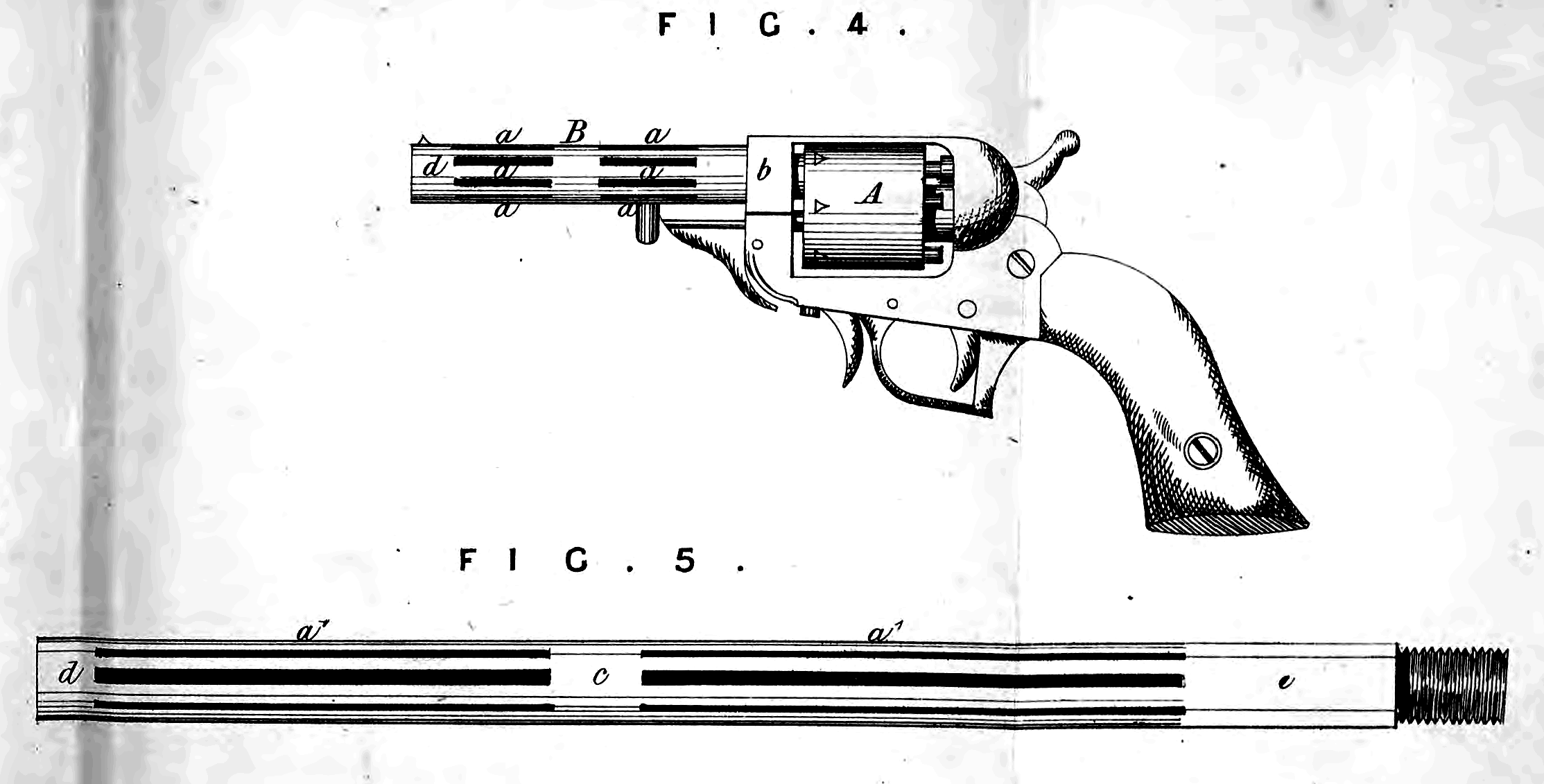
Figure 4 shows a barrel constructed in the manner before described, applied to a revolving pistol; and Figure 5 is a side view of a fixed rifle barrel, with my Invention applied in its construction; in these cases the openings in the barrel are cut or formed in the solid metal.
In applying my Invention to ordnance and fire-arms with revolving or otherwise movable chambers and stationary barrels, I construct the chambers in the usual manner, and make the stationary barrels only or a portion of the same of the skeleton construction, as illustrated by Figure 3. In this Figure, A represents the chambered breech, and h9 h, the chambers ; B is the stationary barrel, represented as having nearly its whole length of skeleton construction, the openings being arranged in two series a, a, and a1, a1, of nearly equal length; those of each series being at equal distances apart all round the barrel, and the barrel being left whole for some distance from the chamber, as shown at b9 between the two series of openings, as shown at c, and at the muzzle, as shown at d.
In applying my Invention to ordnance and fire-arms with fixed chambers forming portions of the barrel or otherwise, the same arrangement of openings in two series a, a, and a\ a\ may be adopted; the first series af a, commencing a short distance in front of the chamber e, and extending nearly half way to the muzzle d; and the next series a\ a\ commencing a short distance in front of them, and extending nearly to the muzzle, and a small portion of the length of the barrel between the two series being left whole, as shown at c; but with either construction of the chamber or chambers the openings may be constructed in a single series, or in more than two series, according to the length of the barrel, or as may be required to give the barrel the requisite strength.
In adapting the Invention to ordnance and fire-arms with rifled bores, the openings a, a, a\ a}, may be of the same width as and coincide with the rifle grooves, so that the lands of the bore are continuous throughout the whole length of the barrel.
My Invention also consists in the combination of such barrels with a revolving breech to produce revolving cannons and other fire-arms free from the danger of heating and explosion; also in working the revolving breech in cannons and ordnance by means of a horizontal lever.
My Invention further consists in the employment with cannon and field pieces of a ball-proof shield ; this shield is made of plates of steel or other suitable metal, in the form of planks hinged to one another, and capable of folding to occupy little space. The back of part of the shield may rest against the wheels of the field-piece, and the screen is further supported by rods connected to the axle nave of the wheels or other convenient part of the carriage. I let into the shield sight-holes formed of wire net.
Figure 6 is a longitudinal section of a field-piece with my improvements applied to it, more particularly indicating the ball-proof shield, with other parts of the mechanism not shown in the previous Figures ; Figure 7 is a plan, and Figure 8 a back view of the same.
Figure 9 is a transverse section of the breech taken through the line #, a?, in Figure 7* Similar letters of reference indicate corresponding parts in these as well as in Figures 1, 2, and 3.
A, A, B, C, D, E, is the carriage constructed like any ordinary gun carriage, except that there is a greater space between the side pieces A, A, to make room between them for the quadrangular wrought iron or other metal frame F, to the front of which is rigidly secured the fixed barrel G, and which receives within it the rotating many-chambered cylinders H; this frame has passing longitudinally through it the axis pin a, upon which the cylinder H rotates, and it has formed upon or secured rigidly to its sides the trunnions 6, b, of the gun, which are fitted, to bearings p, p, in the side pieces A, A, of the carriages, in the same manner as though formed in the body of the gun itself in the usual manner. The said frame has applied under its rear end an elevating screw J, by which the elevation of the gun is adjusted in the same manner as that of an ordinary gun, the trunnions 5, b9 moving in their bearings in such adjustment, in the same manner as those of an ordinary gun. K, K1, is the folding screen composed of two separate divisions, of which one division K is shewn in Figures 7 and 8, in the condition and position in which it is used to protect the artillerymen, and the other K1, in the condition and position in which it is placed to transport the gun from place to place, or when the gun is not in action. Each of the divisions K is composed of a number of panels c, c, of sheet iron arranged side by side and hinged together, and to the sides of a narrow flat bar d of stouter iron by means of hinges e, ey which enable them to fold like the folding shutters used in houses. Each of the said divisions has its bar d connected by a hinge joint / at its back with one of two brackets L, L, which are secured rigidly to the axle B, one outside of each side piece A of the carriage, the said brackets projecting forward far enough to allow the divisions K, K1, to stand up in front of their respective wheels, and of the cylinder frame F, as illustrated by K, in Figures 6, 7, and 8. The two divisions K, K1, are of such width that when they spread they will meet opposite the centre of the gun, and will extend laterally beyond the wheels L\L\ of the carriage, and each is furnished with a number of pivoted socking pieces g, g, so applied as to keep the panels c, c, spread in a comparatively rigid condition, and the outer panel of each has attached to it, by a link joint, a hooked brace h to hook into a hole provided for it, in and near the end of the axle, outside of its respective wheel, to hold it firm with a slight backward inclination in an upward direction, as shewn in Figures 6 and 7, and to keep one or more of the panels of each division at an angle laterally to the principal portion of the screen, as shown in Figure 7, to partly cover the wheels and cause any bullets that may strike them to glance off laterally. A suitable opening is left at the junction of the two divisions K, K1, for the barrel G to pass through, and another opening l above to form a peep-hole through which to sight the gun, and when the two divisions are spread they are connected by one or more locking pieces m, pivoted to one, and dropping into a hook provided for it on the other, such locking piece making them form a complete screen, which is comparatively rigid, but to some extent elastic or yielding, so that bullets may have a less penetrating effect upon it. When the gun is to be transported from place to place at a distance, or is no longer in action, the braces h, h, are unhooked from the axle, the locking piece m is unfastened and the locking pieces g, g, are shifted to such positions as to allow the several panels of each division of the screen to be folded up like a folding shutter, in which condition its upper part is allowed to fall back on the hinge joint / to the position in which it rests on the top of the axle B between the outside of its respective side piece A and an upright pin n, which serves as a guard to keep it clear of the adjacent wheel, as illustrated by K1, in Figures 7 and 8, in which condition and position it does not interfere with the transportation of the gun. The chambers q9 q9 of the cylinder H are bored right through the rear of the said chamber, and the rear portion of the frame F constitutes a breech to that chamber, which is at any time in line with the fixed barrel G. The axis pin a is arranged parallel with the bore of the barrel G, and at such a distance above the said barrel that a chamber in line with the barrel is directly under the said pin. The axis pin has the portion which is received within the front part of the frame F cylindrical, but larger than the portion which passes through the cylinder, so that it fits up to the front end of the cylinder with a shoulder r9 as shown in Figure 6, and the so enlarged part of the said pin is made with a feather or fin to prevent the said pin from turning in the frame F. The rear end of the said pin protrudes through the rear end of the frame, and has a screw thread cut upon its exterior for the reception of a nut M, which is provided with a lever or handle to enable it to be turned by hand for the purpose of drawing back the shoulder r against the front end of the cylinder, and so drawing back the cylinder against the rear end of the frame F, when a plate is pressed forward by the screw pressing tight against the charged chamber, the touch-hole going through this screw and plate, which constitute the breech, and make a gas-tight joint. The cylinder is fitted between the ends of the frame F, so that when the nut M is unscrewed sufficiently to relieve the forward end of the cylinder of the pressure of the shoulder r, the cylinder will just turn freely within the said frame. The rear end of the frame F constituting the breech is provided with a nipple s or priming tube, and bent to enable the charge in the chamber opposite the stationary barrel G, to be fired. The cylinder F has turned in it at its rear end a rebate t, Figure 6, for the reception of a ring N, Figures 6, 7, 8, 9, which is fitted snugly thereinto flush with the rear end of the cylinder, and this cylinder is connected by a fork and pin uy u\ with a lever 0, which works laterally to the carriage under the frame F, on a fulcrum pin v, secured in the front part of the said frame, the said lever serving to turn the said ring upon the cylinder; and the said ring has attached to it, by a spring wl, a tooth w, Figure 9, which works through a hole in the said ring, and enters notches y, y9 in the said cylinder, the said notches being at equal distances apart, and corresponding in number with the number of chambers q9 q. The tooth w is beveled on one side to enable it to slip out of the notches y9 y9 when the ring is turned in the direction of the arrow 5, Figure 9, and thus to enable the ring to move independently of the cylinder in that direction; but the said tooth compels the cylinder to turn with the ring when it engages in one of the said notches, while the ring is turned in the opposite direction. To prevent the cylinder being moved with the ring by the friction between them when the ring is moved in the direction of the arrow 5, a stop pin z, Figure 9, is arranged to slide through a hole provided for it in one side of the frame F, and enter, one by one, the notches y, y, in the cylinder, and this stop pin has applied to it a spring Zl, which tends to press it towards the cylinder, and force it into the said notches as they severally arrive opposite to it. This stop pin is withdrawn by hand from the notches, when it is desired to turn the cylinder to carry one chamber out of line with the barrel, and bring the next chamber in line therewith. A slot Z2 is provided in the ring N to allow it to move upon the stop pin Z, far enough to present the several chambers successively in line with the barrel.
The several chambers of the cylinder are loaded from their rear, while their rear ends are exposed in an open condition above the rear of the frame F, and the loaded chambers are successively brought between the breech and stationary barrel by a movement of the lever 0, first to the right and then to the left. The movement of the said lever to the right turns the ring N upon the cylinder in the direction of the arrow 5, causing the pin u to pass out of one notch y to the next one above it. The stop pin z is then withdrawn by hand from the notch y in which it has engaged, and the lever moved to the left, which turns the ring in the opposite direction, and causes the pin u to bring the cylinder along with it, as indicated by the arrow 6, shewn upon the cylinder in Figure 6, thus removing one chamber out of line with the barrel, and bringing another, which is loaded, in line therewith. The stop pin z may be released as soon as the movement of the lever to the left has commenced, and when the loaded chamber arrives opposite to the barrel, the spring z1 slips into a new notch y, and locks it in that position ready to have the charge contained in it fired by a hammer properly applied, to strike a percussion cup, which has been placed on the nipple $, or by any other suitable means. Before firing, the nut M is tightened up to tighten the breech joint, as before described, and this must be slackened again before the next movement of the cylinder can be effected; the movement of the lever 0 is properly limited by means of a fixed yoke P, secured to the bottom of the frame F, but such yoke is not absolutely necessary. The said yoke, however, constitutes a convenient bearing for the elevating screw J.
And having now described the nature of my said Invention, and in what manner the same is to be performed, I declare that I claim as my improvements in constructing the barrels of fire-arms and ordnance, and in fire-arms,—
First, the construction of the barrels of fire-arms and ordnance with longitudinal parallel openings in them, whether such openings extend the whole or only part of the length of the barrel, as herein-before described and illustrated in the accompanying Drawings.
Second, the combination of skeleton barrels with a revolving breech, substantially in manner and for the purposes herein-before described with reference to the accompanying Drawings.
Third, the construction and employment of a folding screen applied to a breech-loading field-piece, or other piece of ordnance, substantially as hereinbefore described and illustrated in the accompanying Drawings.
Fourth, the arrangement of the rotating many-chambered cylinder in~a frame F, which has the fixed barrel 6 rigidly attached to it, when the said frame is furnished with trunnions fitted to bearings in the carriage, and has the elevating screw applied to it, substantially as herein-before described and illustrated in the accompanying Drawings.
Fifth, the employment of an axis pin o, having a shoulder r, and fitted to the cylinder frame F, and rotating many-chambered cylinder, substantially as herein-before described, and furnished with a screw thread receiving a nut M applied in the rear of the cylinder frame, to operate substantially as herein set forth, for the purpose of making a tight joint between the open rear of the chambers, and a breech formed by the rear end of the cylinder frame.
Sixth, the combination with the rotating many-chambered cylinder H of the ring N, the lever 0, the spring tooth tv and the stop pin z 5 the said tooth and pin operating in combination with notches y, y, in the cylinder, substantially as and for the purpose herein-before described and illustrated in the accompanying Drawings.
Seventh, the employment of a screw and plate in the frame with the touch-hole going through the said screw and plate horizontally, as herein-before described.
In witness whereof, I, the said John Andrew Van Braam, have hereunto -set my hand and seal, this Fourteenth day of November, One thousand eight hundred and sixty-one.
J. A. V. BRAAM. (l.s.)