
Britain 716
A.D. 1881, 19th February, № 716.
Repeating Fire-arms and Revolvers, &c.,
LETTERS PATENT to John Jepson Atkinson, of the Middle Temple, in the City of London, Barrister-at-Law, and Joseph Needham, of Hammersmith Terrace, in the County of Middlesex, Gun Maker, for an Invention of “Improvements in Repeating Fire-arms and Revolvers and in Cartridges therefor, which Cartridges are Applicable to other Descriptions of Fire-arms.”
PROVISIONAL SPECIFICATION left by the said John Jepson Atkinson and Joseph Needham at the Office of the Commissioners of Patents on the 19th February 1881.
John Jepson Atkinson, of the Middle Temple, in the City of London, Barrister at Law, and Joseph Needham, of Hammersmith Terrace, in the County of Middlesex, Gun Maker, “Improvements in Repeating Fire-arms and Revolvers and in Cartridges therefor, which Cartridges are Applicable to other Descriptions of Fire-arms.”
The Invention relates, firstly, to improvements in repeating fire arms, and consists of means whereby great strength, simplicity, and certainty of action combined with cheapness of construction are obtained.
For this purpose, according to one arrangement, we mount at the breech end of the repeater on a pin, with capability of revolving thereon, a block containing two chambers and provided with a cam at the end, which raises and lets fall the hammer for firing and intermediate thereof, whereby the hammer. is caused to eject the empty cartridge at the first quarter turn of the block, and then to assume a position of full cock when a further slight turn of the block brings the loaded chamber opposite the barrel and lets fall the hammer to explode the cartridge. We actuate this block and consequently the cam by means of a driver acting upon a ratchet wheel or upon teeth or projections formed on or fixed to the cam or block. This driver may either be connected to the trigger, and so by one continuous pull turn the cam and block and operate the hammer, or it may be connected to a lever, Which forms the trigger guard, and in that case we propose to have a trigger which is out of the way until the hammer is at full cock, then when by an up and down motion of the said lever the block has received a complete half turn, the nose of the trigger slips into the “bent,” and the trigger comes into firing position.
The driver may be formed double to act on each side of the ratchet wheel so as to act at both the up and down motion of the lever, thereby enabling the latter to give the desired motion to the block whilst moving a shorter distance than when acting only in one direction.
Or in lieu of operating the block as above described, the ordinary revolver action may be employed to revolve said block and to lift and Jet fall the hammer, in which case however the hammer is also operated, as above described, to eject the spent cartridge.
The hammer in each case is of » similar character to that used in the so called “hammerless gun,” and the spring for acting upon the hammer is that usually employed, except that the lower limb of the spring is caused to press on the trigger and keep it in position, thereby obviating the necessity for a second spring to restrain the trigger, although if desired a spiral or other spring may be used for operating the hammer or striker, as described in the Specification of Letters Patent granted to one-of us, the said Joseph Needham, dated October 2, 1852, No. 184.
The rotating cam for acting upon the hammer as above described is also applicable to revolver fire arms, thereby securing greater simplicity in the construction thereof.
In the arrangements above described when one-chamber in the breech block is in-a line with the barrel, the other chamber is in position to receive a cartridge from the magazine, which latter lies underneath the barrel of the repeater.
Instead however of employing a revolving breech block provided with two chambers as above described, more than two such chambers.may be employed, and we sometimes employ a breech block, mounted at its rear end on a horizontal axis across the end of the barrel, so as to enable the same to be moved up and down in a vertical plane in line with the barrel, and such breech block is provided with only one chamber; this breech block is operated by a lever, as before described, to place the chamber thereof in position to receive a cartridge from the magazine and afterwards in line with the barrel whilst the said lever also operates the sear. This last mentioned breech block is bored to receive a firing pin, which latter also acts as an ejector. The operating lever by means of a tooth or projection acts upon a link or lever pin, jointed to a projection from the breech block to lower the latter from the firing position to the position for ejecting the spent cartridge, in which latter position the firing pin, having been forced forward by a tail piece thereon, coming against a fixed part of the action body, ejects the cartridge, then in the continued motion of the operating lever in the same direction projection on the latter forces the breech block up into line with the magazine, and another projection or pin on the operating lever acts within a groove in the breech block to hold the latter firmly during the insertion of a cartridge therein from the magazine, then in the continued motion of the operating lever a nose or projection on the latter acts against an incline on the breech block to raise the latter to and hold it in the firing position. A projection, before referred to, on the operating lever acts upon the hammer in the descent of the breech block to place the said hammer at full cock, and said hammer acts upon the tail piece before described of the striker, to draw the latter back away from the cartridge as the cartridge is being carried into line with the barrel, then at the last portion of the motion of the operating ever the said lever presses the lower end of the sear and thereby liberates the hammer.
The magazine, as before described, lies underneath the barrel in line therewith, and we employ a pusher between the spring and the cartridges, said pusher being provided with a knob or projection passing through a longitudinal slot formed in the magazine, and with a catch to enable the pusher when the spring has been fully compressed for the insertion of fresh cartridges into the magazine to be held during such insertion. And in order to facilitate the loading of the magazine we in some cases form a portion of the magazine tube removeable, and provide such part with a spring catch at each end to hold the cartridges therein when not in position on-the repeater. In placing such removeable part in position these end catches are by fixtures pressed outwards to release the cartridges, and the said removeable part is held in position by suitable catches provided for such purpose. In repeating pistols we form the entire magazine a fixture or mount it on a pin joint at the forward end thereof whilst it is charged at its open rear end.
Instead however of forming the breech block.with only one chamber, as above described, it may be formed circular and with chambers entirely around the same, in which case it will be caused to travel always in the same direction on an axis across the end of the barrel, thereby forming an efficient revolver capable of being used with or without the magazine, which we in such case place on the top of the barrel. The cam for acting on the hammer is formed or fixed on one side of the chamber and acts in a similar manner to that herein first described, except that the position thereof is changed and its form suitably modified.
Our improvements in cartridges for the above description of repeaters and revolvers and for other fire arms where it is necessary to prevent the escape of gas both at the front and rear end of the breech block, consist in forming the cartridge case with a plain rear end provided with the ordinary central fire cap and without a flange at such end, whilst at the front end thereof we employ a cap bored to permit of the passage of the ball or shot, but which by expanding and being forced against the breech end of the barrel will prevent the escape of gas at such part.. The cap above described is also applicable to cartridges for other fire arms requiring a similar gas check at the front of the cartridge.
SPECIFICATION in pursuance of the conditions of the Letters Patent filed by the said John Jepson Atkinson and Joseph Needham in the Great Seal Patent Office on the 19th August 1881.
John Jepson Atkinson, of the Middle Temple, in the City of London, Barrister at Law, and Joseph Needham, of Hammersmith Terrace, in the County of Middlesex, Gun Maker. “Improvements in Repeating Fire-arms and Revolvers and in Cartridges therefor, which Cartridges are Applicable to other Descriptions of Fire-arms.”
The Invention relates, firstly, to improvements in repeating fire arms, and consists of means whereby great strength, simplicity, and certainty of action combined with cheapness of construction are obtained.
For this purpose, according to one arrangement, we mount at the breech end of the repeater on a pin with capability of revolving thereon a block containing two chambers and provided with a cam at the end which raises and if desired lets fall the hammer for firing and intermediate thereof, whereby the hammer is caused to eject the empty cartridge at the first quarter turn of the block and then to assume a position of full cock, when a further slight turn of the block brings the loaded chamber opposite the barrel, and if desired lets fall the hammer to explode the cartridge. We actuate this block and consequently the cam by means of a driver acting upon a ratchet wheel or upon teeth or-projections formed on or fixed to the cam or to the block.
This driver may either be connected to the trigger and so by one continuous pull turn the cam and block and operate the hammer, or it may be connected to a lever which forms the trigger guard, and in that case we propose to have a trigger which is out of the way until the hammer is at full cock, then when by an up and down motion of the said lever the block has received a complete half turn the nose of the trigger slips into the “bent” and the trigger comes into firing position.
The driver may be formed double to act on each side of the ratchet wheel so as to act at both the up and down motion of the lever, thereby enabling the latter to give the desired motion to the block whilst moving a shorter distance than when acting only in one direction.
Or in lieu of operating the block as above described the ordinary revolver action may be employed to revolve said block and to lift and let fall the hammer, in which case however the hammer is also operated as above described to eject the spent cartridge.
The hammer in each case is of a similar character to that used in the so called “hammerless gun,” and the spring for acting upon the hammer is that usually employed, except that the lower limb of the spring is caused to press on the trigger and keep it in position, thereby obviating the necessity for a second spring to restrain the trigger, although if desired a spiral or other spring may be used for operating the hammer or striker, as described in the Specification of Letters Patent granted to one of us, the said Joseph Needham, dated October 2, 1852, No. 184.
The rotating cam for acting upon the hammer as above described is also applicable to revolver fire arms, thereby securing greater simplicity in the construction thereof.
In the arrangements above described when one chamber in the breech block is in a line with the barrel the other chamber is in position to receive a cartridge from the magazine, which latter lies underneath the barrel of the repeater.
Instead however of employing a revolving breech block provided with two chambers as above described, more than two such chambers may be employed, and we sometimes employ a breech block mounted at its rear end:on a horizontal axis, across the end of the barrel so as to enable the same to be moved up and down in a vertical plane in line with the barrel, and such breech block is provided with only one chamber. This breech block is operated by a lever as before described to place the chamber thereof in position to receive a cartridge from’ the magazine and afterwards in line with the barrel, whilst the said lever also operates the sear, This last mentioned breech block is bored to receive a firing pin, which latter also acts as an ejector. The operating lever by means of a tooth or projection acts upon a link or lever pin-jointed to a projection from the breech block to lower the latter from the firing position to the position for ejecting the spent cartridge, in which latter position the firing pin having been forced forward by a tail piece thereon coming against a fixed part of the action body ejects the spent cartridge, then in the continued motion of the operating lever in the same direction a projection on the latter forces the breech block up into line with the magazine, and another projection or pin on the operating lever acts within a groove in the breech block to hold the latter firmly during the insertion of a cartridge therein from the magazine; then in the continued motion of the operating lever a nose or projection on the latter acts against an incline on the breech block to raise the latter to and hold it in the firing position. A projection before referred to on the charge chamber block acts upon the hammer in the descent of the breech block to place the said hammer at full cock, and said hammer acts upon the tail piece before described of the striker to draw the latter back away from the cartridge as the cartridge is being carried into line with the barrel; then at the last portion of the motion of the operating lever the said lever presses the lower end of the sear and thereby liberate the hammer.
The magazine as before described lies underneath the barrel in a line therewith, and we employ a pusher between the spring and the cartridges, said pusher being provided with a knob or projection passing through a longitudinal slot formed in the magazine and with a catch to enable the pusher when the spring has been fully compressed for the insertion of fresh cartridges into the magazine to be held during such insertion.
In repeating pistols we form the entire magazine a fixture or mount it on a pin joint at the forward end thereof whilst it is charged at its open rear end.
Our improvements in-cartridges for the above description of repeaters and revolvers and for other fire arms where it is necessary to prevent the escape of gas, both at the front and rear ends of the breech block, consist in forming the cartridge case with a.plain rear end provided with the ordinary central fire cap, and without a flange at such end, whilst at the front end thereof we employ a cap bored to permit of the passage of the ball or shot, but which by expanding and being forced against the breech end of the barrel will prevent the escape of gas at such part. The cap above described is also applicable to cartridges for other fire arms requiring a similar gas check at the front of the cartridge.
And in order that our said Invention may be more clearly understood and readily carried into effect, we will proceed, aided by the accompanying Drawings, more fully to describe the same.
DESCRIPTION OF THE DRAWINGS.
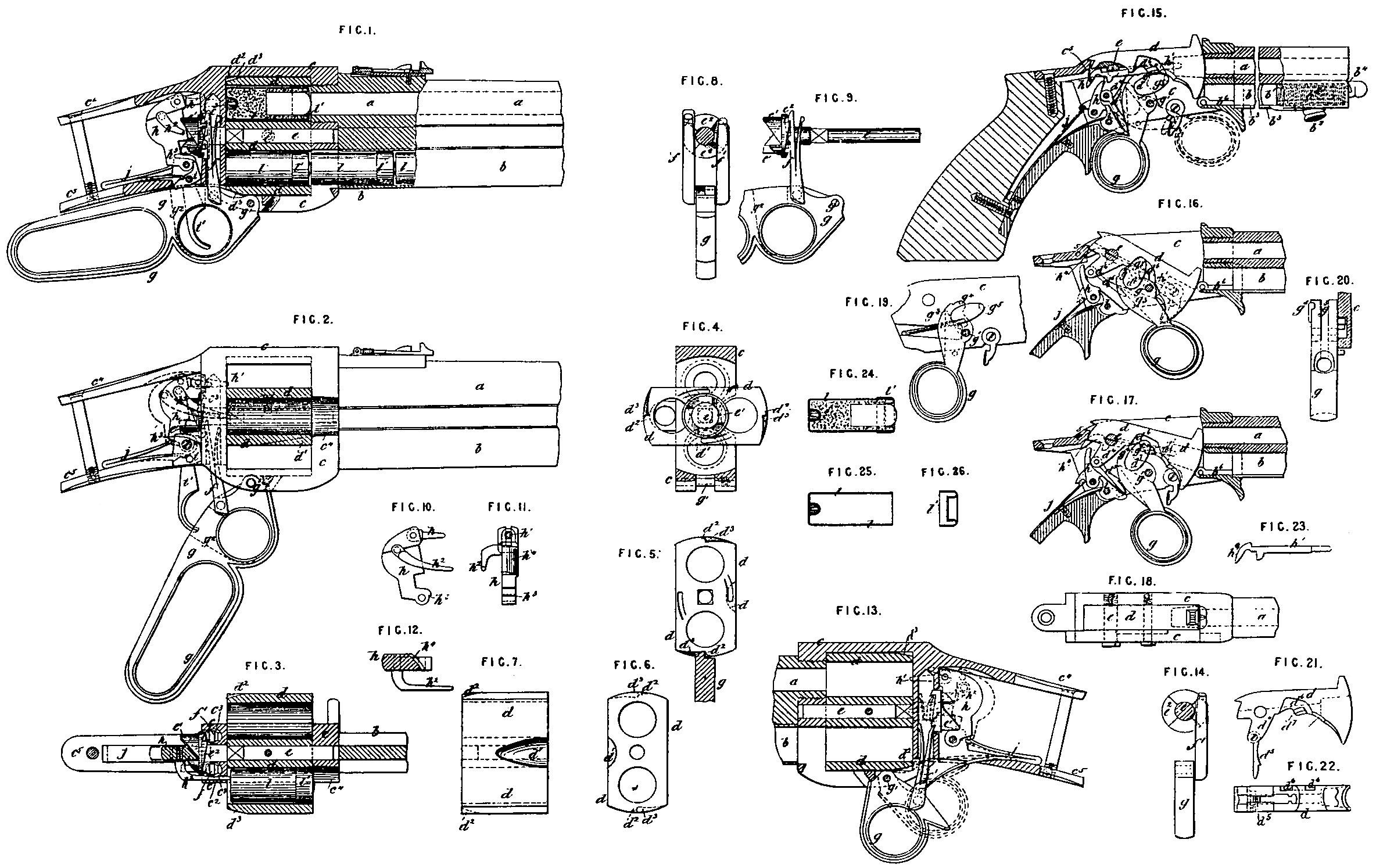
Figure 1 is a sectional elevation, of parts of a repeating fire arm constructed according to our Invention; Figure 2 is a side elevation, partly in section; and Figure 3 is a plan in section showing the charge chamber block in a horizontal position, with the ejector in the act of ejecting a spent cartridge from a charge chamber; Figure 4 is a cross section of parts, showing an end view of the charge chamber block in a horizontal position; Figures 5 and 6 are opposite end views of the charge chamber block in the firing position, Figure 5 showing it gripped by the upper edge of the operating lever; Figure 7 is a side view of such block; Figure 8 is a fore end elevation, and Figure 9 1s a side elevation of parts of the operating lever, with its drivers in position against the ratchet wheel; and Figures 10, 11, and 12 are respectively a side elevation, front elevation, and horizontal section of the hammer or striking lever, with the ejector carried thereby.
Figures 13 and 14 represent respectively a side and an end elevation of a slight modification of parts, whereby a separate trigger or operating lever is dispensed with; Figure 15 is a sectional elevation of a repeating pistol constructed according to our Invention, representing the parts in the position they would assume immediately after having been fired; Figure 16 is a sectional elevation of the same, showing the parts in position for ejecting a spent cartridge; Figure 17 is a sectional elevation of the same, showing the charge chamber block in position for receiving a cartridge from the magazine tube; Figure 18 is a plan of parts, Figure 19 is a side elevation, and Figure 20 is a front elevation, partly in section, of the operating lever and part of the breech frame.
Figure 21 is a side elevation, and Figure 22 is an underside view of the charge chamber block separately; and Figure 23 is a side elevation of the firing pin separately.
Figure 24 is a longitudinal section of our improved cartridge to be used with fire arms constructed according to our Invention, and which is applicable to other fire arms in which a gas check is required at both the back and front of the cartridge; Figure 25 is a longitudinal section of the cartridge case separated from the front end, a section of which latter is shown separately at Figure 26.
a represents the barrel of the gun, and b a tubular magazine fixed along the underside of the barrel a; said magazine may be charged in any suitable and well known manner, and it may have a spring follower to act against the cartridges therein, but we find that it acts well without a spring follower if made large enough to permit a free motion of the cartridges therein, and it may be readily loaded from the breech end thereof by turning the gun over so as to place the magazine upper-most, and in an inclined position with the muzzle downwards, and by turning the charge chamber block d in a cross position, with the side groove d¹ towards the magazine b; then by dropping the cartridges through the aperture c¹ in the metal frame c they will readily run into and down the magazine b, The groove c⁴ in the frame c allows of the ejection of the spent cartridge, and also of the gun being used as an ordinary breech loader when required.
The charge chamber block d is provided with a stud or axis e fixed rigidly therein, and working in suitable bearings formed for it in the front and rear portions of the frame c. On the rear end of the stud or axis e is formed or fixed a cam e¹ and ratchet wheel e², which latter is acted upon by drivers f, f¹, attached to a lever g mounted on an axis of motion at g¹. The driver f acts upon the ratchet wheel e² when descending, and the driver f¹ acts upon such wheel in rising, so that the lever g in descending causes the driver f to give a quarter turn to the charge the lever g in descending causes the driver f to give a quarter turn to the charge chamber block d, and in rising causes the driver f¹ to give another quarter turn to such block, thereby reversing the position of the charge chambers thereof.
h is the hammer lever, to which the striker h¹ is pin jointed; such hammer lever also carries an ejector pin h², which works in a hole c² formed in the frame c, and it is formed with a “bent” h³ to act in combination with the sear i. One arm of the spring j acts upon the hammer lever h, and the other arm upon the “sear” i. The hammer lever h is also formed with an inclined face h⁴ to act in combination with the projections on the cam e¹.
The drivers f, f¹ work in holes c³ drilled in the frame c, and are kept up to their work by springs formed on such drivers, as shown.
The trigger i¹ works in a slotted hole g² formed in the lever g and shown by dotted lines.
The frame c is formed with an aperture in which the charge chamber block d works, and it is connected to the barrel a by being screwed thereon as shown; the frame c is also formed with tangs c⁴, c⁵, by which it is connected to the stock.
The action of the gun is as follows:— The parts being in the position shown at Figure 1, the gun is ready for firing, which can be done by pulling the trigger i¹.
After having been fired the gun is again prepared for firing in the following manner:— The lever g is depressed to the position shown at Figure 2, during which action the driver facts upon the ratchet wheel e², and thereby turns the charge chamber block d a quarter revolution, thereby bringing it into the position shown at Figures 2, 3, and 4. During such downward motion of the lever g one of the shorter projections of the cam e¹ acts upon the hammer lever h to force it back to the position shown by dotted lines in Figures 2 and 3, after which at the completion of such quarter turn the hammer lever h will have slipped off such projection, and by the ejector h² will have ejected the spent cartridge from the charge chamber which was last fired; then by again raising the lever g into the position shown at Figure 1, the driver f¹ will act on the ratchet wheel e² and give another quarter turn to the block d, and will thereby bring the charge chamber (which at the last firing was in a line with the magazine b) into a line with the barrel a, and during such motion one of the larger projections on the cam e¹ will have forced back the hammer lever h into the, firing position so that it is held by the sear i until it is desired to fire the charge.
When an empty charge chamber is in line with the magazine b the said charge chamber can be readily loaded by simply raising the muzzle end of the gun, when a cartridge will fall into the said charge chamber from the magazine b, or if the latter is provided with a spring follower to act upon the cartridges an empty charge chamber will be loaded directly it is presented to the magazine b, whatever position the gun may be held in at the time.
If desired, the gun above described can be used as an ordinary breech loader, in which case a charge chamber can be loaded whenever it comes in line with the groove or recess c⁶ in the right hand side of the frame c shown in Figures 2 and 3.
The charge chamber block d is correctly adjusted and held in position for firing by stops d² formed thereon coming against the upper edge of the operating lever g which latter grips the said block firmly by entering the depressions d³ formed against the stops d³.
Instead of employing a separate trigger i¹ and a separate operating lever g as above described, the arrangement shown at Figures 13 and 14 may be adopted, which arrangement requires the operating lever to be pulled twice to give the required motion to the charge chamber block d and other parts whilst the trigger i¹, sear i, and bent h³ of the first described arrangement are dispensed with, and the cam e¹ is caused to lift and let fall the hammer h at the required times for firing and for ejecting the spent cartridge.
The above described method of operating the charge chamber block and hammer and of ejecting the spent cartridge is also applicable to revolvers, in which case the charge chamber block d would preferably be made with more than two charge chambers, but in such case the motion of the driver f¹ would require to be adjusted to the amount of motion required to be given to the charge chamber block d, We have not thought it necessary to give Drawings of this last described application of our Invention, as such will be readily understood by a competent mechanic.
The method hereinbefore described of ejecting the spent cartridge is also applicable to repeating fire arms and revolvers provided with a different action from that above described.
We will now describe the arrangement represented at Figures 15 to 23 inclusive, which is applicable to pistols and other small arms, a represents the barrel; b, the tubular magazine fixed underneath the same; c, plates or frame connecting the barrel to the stock; and d the charge chamber block which is mounted at its rear end on a horizontal axis e across the end of the barrel a, so as to enable the same to be moved up and down in a vertical plane in line with the barrel, and such charge chamber block is provided with only one chamber; this charge chamber block is operated by a lever g mounted on an axis g¹ to place the chamber thereof in position to receive a cartridge from the magazine b, as shown at Figure 17, and afterwards in line with the barrel a, whilst the said lever when brought into the position shown at Figure 15, also operates the sear i. The charge chamber block d is bored to receive a firing pin or striker h¹; which latter also acts as the ejector. The operating lever g, by means of a tooth or projection g³, acts upon a link or lever d⁵, pin jointed to a projection d⁴ from the charge chamber block ad to lower the fore end of the latter from the firing position to the position for ejecting the spent cartridge, as shown at Figure 16, in which latter position the firing pin or striker h¹ having been forced forward by a tail piece h⁴ thereon coming against a fixed part c⁵ of the action body ejects the spent cartridge, then in the continued motion of the operating lever g in the same direction, a projection g⁴ on the latter forces the charge chamber block d up into line with the magazine tube b, as shown at Figure 17, and another pin or projection g⁵ on the operating lever g acts within a cam shaped groove or recess d⁶ in the charge chamber block d, to hold the latter firmly in such position during the insertion of a cartridge therein from the magazine tube b, then in the continued motion of the operating lever g, the nose or projection g⁴ on the latter acts against an incline d⁷ on the charge chamber block d to raise the latter to and hold it in the firing position. The projection d⁴ on the charge chamber block d acts upon the hammer lever h in the descent of the said block a to place the said hammer lever at full cock, and said hammer lever acts upon the tail-piece h⁴ of the striker pin h¹ to draw the latter back away from the cartridge as the cartridge is being carried into line with the barrel a, then at the last portion of the motion of the operating lever g the back of the said lever g presses the lower end of the sear 4 and thereby liberates the hammer lever h, which being then urged forward by the spring j forcibly strikes against the projection h⁵ on the striker pin h¹, and thereby causes the latter to fire the cartridge.
The magazine b is provided with a pusher b¹ between the spring b⁵ and the cartridges, said pusher being provided with a knob or projection b² passing through a longitudinal slot b³ formed in the magazine, and with a catch b⁴ to enable the pusher b¹, when the springs b⁵ has been fully compressed, as shown, for the insertion of fresh cartridges into the magazine b, to be held during such insertion.
The magazine b is represented in the Drawings as a fixture and to be provided with a hinged piece b⁶ at the rear end, which when turned down enables the said magazine to be readily charged. Instead, however, of making the said magazine tube b a fixture, it may be mounted on a pin joint at its forward end and be retained in position for use by spring catches which permit it when required to be turned on its pin joint for charging the same with cartridges. We have not thought it necessary to give a Drawing of this arrangement, as such will be readily understood by a competent mechanic.
And in order to facilitate the loading of the magazine we in some cases form a portion of the magazine tube removeable, and provide such part with a spring catch at each end to hold the cartridges therein when not in position on the repeater, In placing such removable part in position, these end catches are, by fixtures, pressed outwards to release the cartridges, and the said removable part is held in position by suitable catches provided for such purpose, as will be readily understood.
We would here remark that the arrangement of revolver pistol described in our Provisional Specification, having a revolving charge chamber mounted on & horizontal axis fixed across the breech end of the barrel and revolving in a vertical plane, does not possess such an amount of novelty or utility as to render it desirable further to describe the same, and for this reason we desire to disclaim and we do hereby disclaim such arrangement.
Fire arms constructed as above described, require cartridges which shall prevent the escape of gas both at the fore and breech ends of the charge chamber block, and our improved cartridges are shown in position in the fire arm at’ Figure I, and separately at Figures 24, 25, and 26. The cartridge case l is constructed as heretofore of a tube or cylinder closed at one end and provided with a recess in which the ordinary central fire cap is fixed, but we form such rear end without a flange so as to enable the cartridge to be inserted into the charge chamber from the fore end thereof, and we place on the fore end of the cartridge case l an annular cup shaped cap l¹ formed to fit tightly the cylinder l, and provided with an opening in the centre thereof to permit of the passage of the ball or shot, but which by expanding and being forced against the breech end of the barrel will prevent the escape of gas at such part. The cap l¹ above described is also applicable to cartridges for other fire arms requiring a similar gas check at the front of the cartridge.
If desired, the cap l¹ may be formed in one piece with the cartridge case or cylinder by turning the metal at the front end of such cylinder inwards so as to form an inwardly projecting flange with a hole therein for the passage of the bullet or shot.
Having thus described the nature of our said Invention and the mode in which we carry the same into effect, we would have it understood that what we claim is,—
First. The general arrangement, combination, and method of working of the parts of repeating fire arms and revolvers, substantially as herein shown and described with respect to Figures 1 to 14.
Second, The arrangement and combination of parts of repeating fire arms and revolvers, for lifting and letting fall the hammer or striker for firing and for ejecting the spent cartridge by means of a cam e¹, substantially as herein shown and described with respect to Figures 1 to 14.
Third. In repeating fire arms and revolvers ejecting the spent cartridges forwards from the charge chamber block by means of the hammer or striker or firing pin, substantially as herein shown and described.
Fourth. In repeating fire arms and revolvers, holding the charge chamber block d in firing position by means of the lever or trigger g, substantially as herein shown and described with respect to Figures 1 to 14.
Fifth. The general arrangement, combination, and method of working of the parts of repeating fire arms, substantially as shown and described with respect to Figures 15 to 23.
Sixth. Constructing cartridges with a gas check at the front end in addition to that at the rear end thereof, and with or without a flange at the rear end, substantially as herein shown and described.
In witness whereof, I, the said Joseph Needham, have hereunto set my hand and seal, this Nineteenth day of August, in the year of our Lord One thousand eight hundred and eighty one.
JOSEPH NEEDHAM. (L.S)