
Britain 3313
A.D. 1881, 29th July. № 3313.
Fire Arms.
LETTERS PATENT to William Edward Gedge, of No. 11, Wellington Street, Strand, London, in the County of Middlesex, Patent Agent, for an Invention of “Improvements in Fire-arms.” A communication from abroad by Michael Kaufmann, of Brussels, Belgium.
PROVISIONAL SPECIFICATION left by the said William Edward Gedge at the Office of the Commissioners of Patents on the 29th July 1881.
William Edward Gedge, of No. 11, Wellington Street, Strand, London, in the County of Middlesex, Patent Agent. “Improvements in Fire-arms.” A communication from abroad by Michael Kaufmann, of Brussels, Belgium.
This Invention relates particularly to a locking device for fastening the barrel to the breech of a revolver.
The top of the breech has a slot of a determined size and shape adapted to receive the end of a bar, which forms a continuation of the barrel at its rear end and called a barre strap.
The end of this barrel strap which fits into the slot of the breech is pierced with a hole, in which there is a moveable pin of the length of the said hole countersunk underneath and fastened with a small screw to prevent the said pin falling out or moving beyond the required distance, and one end of this pin has an inclined plane commencing from its lower surface. One of the sides of the breech near its top is likewise pierced with a hole, in which there is a moveable pia projecting outwards and fastened in a similar manner as that described as fitted in the end of the barrel strap. The other side of the breech and directly opposite is likewise pierced with a hole, in which there is a moveable pin held in its place and functioned by means of a spring attached to the exterior end of this pin and to the frame of the revolver. The interior end of this pin has an inclined plane commencing from its upper surface.
OPERATION.
By pressing with the thumb of the operator on the projecting pin in the breech to which no spring is attached, the said pin is thrust forward in the side of the breech in which it moves until the inner end of this pin is brought flush with the interior of the said side, whilst the said pin bears against a pin partially resting in the aforesaid side of the breech and attached to the barrel-strap, and pushes the latter pin until it is brought flush with both sides of the barrel-strap, which latter pin being thereby brought to bear against that pin attached to the spring in like manner pushes the last named pin outwards until free of the barrel-strap and flush with the interior of the side of the breech in which it moves. The barrel is now free, and by giving it a tilting motion it disengages itself from the breech of the weapon. On swinging the barrel back into its place the lower end of the barrel-strap presses against the pin-attached to the spring and pushes the said pin outwards until the barrel arrives at its normal position, when the spring forces its pin to some extent into the. hole on that side of the end of the barrel-strap, thereby pushing the pin attached to the barrel-strap to some extent into the hole in the other side of the breech. The barrel is then firmly locked.
SPECIFICATION in pursuance of the conditions of the Letters Patent filed by the said William Edward Gedge in the Great Seal Patent Office on the 25th January 1882.
William Edward Gedge, of No. 11, Wellington Street, Strand, London, in the County of Middlesex, Patent Agent. “Improvements in Fire-arms.” A communication from abroad by Michael Kaufmann, of Brussels, Belgium.
This Invention relates to an improved locking device for fastening the barrel to the breech of a fire-arm.
I will now proceed to describe this device in its application to-a revolving pistol.
The top of the breech (A) has a slot (B) of a determined size and shape adapted to receive the end of a bar (C), which forms a continuation of the barrel (D) at its rear end and is called a. barrel-strap. The end of this barrel-strap (C) which fits into the slot (B) of the breech (A) is pierced with a hole (E), in which there is a moveable pin (F) of the length of the said hole recessed underneath, and fastened with a small screw (G) to prevent the said pin falling out or moving beyond the. required distance, and one end of this pin has an inclined plane (H) commencing from its lower surface. One of the sides of the breech (A) near its top is likewise pierced with a hole (I), in which there is a moveable pin (K) projecting outwards and fastened in a similar manner as that described as fitted in the end of the barrel strap. The other side of the breech and directly opposite is likewise pierced with a hole (L), in which there is a moveable pin (M) held in its place and functioned by means of a spring (N) attached to the exterior end of this pin and to the frame of the revolver. The interior end of this pin has an inclined plane (O) commencing from its upper surface.
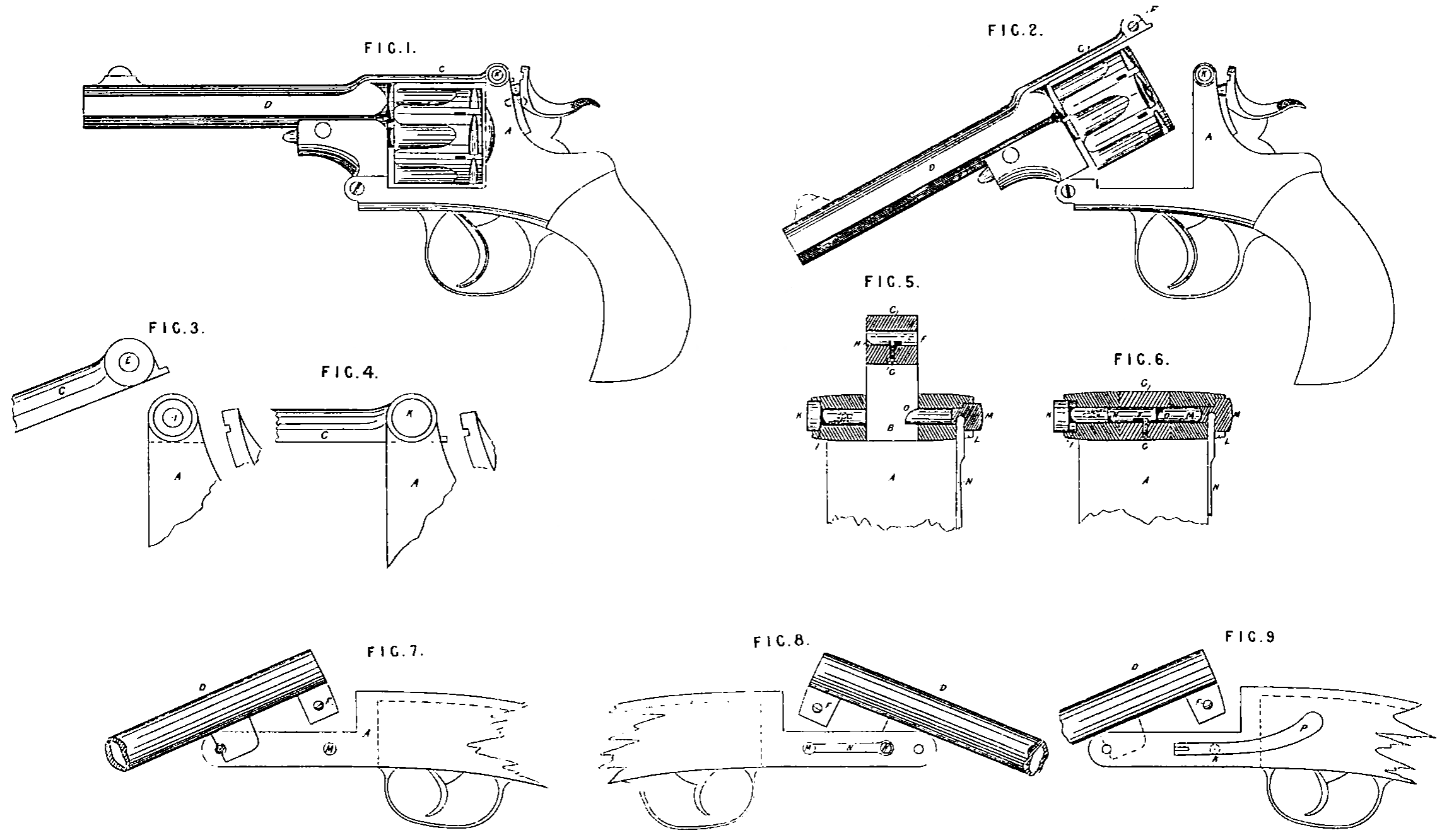
On the accompanying Sheet of Drawing,—
Figure 1 represents a side view of a revolver embodying these improvements,
Figure 2 is a similar view, but with barrel depressed.
Figure 3 is a side view of barrel-strap and portion of breech drawn to an enlarged scale as it appears when thrown up, the pins being removed.
Figure 4 illustrates the position of same when locked.
Figure 5 is a cross section through the above, shewing position of pins when strap is raised.
Figure 6 is a similar view with barrel strap locked in position.
A indicates the breech.
B is slot in same.
C, barrel strap.
D, the barrel.
E, hole in strap C.
F, pin working in hole E.
G, screw.
H, inclined plane on pin F.
I, hole in side of breech A.
K, pin working in hole L.
L, hole in opposite side of breech.
M, pin working in hole L.
N, spring.
O, inclined plane on pin M.
P, lever for operating pin K.
To unlock the barrel from the breech action the operator presses upon the projecting head of pin K, causing the said pin to move in the side of breech A and push forward the pin F, hitherto engaged in same side of breech A; when the inner end of pin K is flush with inner face of breech A the pin F is entirely flush with the barrel strap C in consequence of the motion of the pin F; the pin M actuated by the spring N is entirely withdrawn from its engagement in the said barrel strap. The barrel D is now free and can be disengaged from the breech of the weapon.
On returning the barrel back into its place the lower end of the barrel-strap C presses against the pin M attached to the spring N and pushes the said pin outwards until the barrel arrives at its normal position, when the spring N forces its pin M to some extent into the hole on that side of the end of the barrel strap C, thereby pushing the pin F attached to the barrel strap to some extent into the hole in the other side of the breech. The barrel is then firmly locked.
This improved locking device may also be applied to breech loading snap action guns and rifles on the. drop down system.
To effect this the bolts may be placed below the barrel and made to engage with the lump on the underside of barrel or barrels or any projection from rear end of same in a similar as in the revolving pistol herein before described; said bolts may be operated upon directly by pressure of the operator’s thumb, or a lever may be jointed to actuate bolt, said lever passing over the bolt and beyond to any convenient distance.
By pressing this lever upon bolt, said bolt will be the more easily functioned.
Figure 7 of the Drawing illustrates an application of the above described locking device to a breech loading gun upon the drop down system.
Figure 8 shows position of spring on the opposite side, and
Figure 9 represents an arrangement in which the locking bolt is operated by means of a lever.
Having now described and ascertained the nature of the Invention communicated to me as aforesaid, and in, what manner the same is or may be performed.
I claim as secured to me by the hereinbefore in part recited Letters Patent,—
Firstly. In a revolving breech loading fire-arm the use of the moveable pin F with inclined plane H in the barrel strap in combination with the moveable pins K and M in the breech, the pin M being actuated by the spring N, and the whole constructed and arranged to operate substantially as and for the purpose herein before described.
Secondly: The application of the hereinbefore described improved locking device-breech loading guns or rifles on the drop down system, substantially as herein-before set forth.
In witness whereof, I, the said William Edward Gedge, have hereunto set my hand and seal, this Twenty fifth day of January, in the year of our Lord One thousand eight hundred and eighty two,
W. E. GEDGE. (L.S.)