
Britain 3913
A.D. 1881, 9 September. № 3913.
LETTERS: PATENT to Michael Kaufmann, of No. 11, Wellington Street, Strand, London, in the County of Middlesex, for an Invention of “Improvements In Fire Arms.”
PROVISIONAL SPECIFICATION left by the said Michael! Kaufmann at the Office of the Commissioners of Patents on the 9th September 1881.
Michael Kaufmann, of No. 11, Wellington Street, Strand, London, in the County of Middlesex. “Improvements In Fire Arms.”
My Invention relates specially to. solid frame or rod-extracting revolving fire arms, in which the lock is provided with a rebounding hammer, but is also applicable to other revolving fire arms where the arm is loaded by means of a gate, door, or moveable covering plate at the rear of the cylinder.
The object of my Invention is to provide the lock of such fire arms with a stop which locks the cylinder after each rotation and keeps it securely in place when not in use, an essential feature of my Invention being the utilization of the door. or moveable covering plate for the purpose of freeing the cylinder from said stop go that it may rotate freely when desired in order that the fire arm may be loaded.
I propose to attain my object by so arranging the door or moveable covering plate that when operated by being opened to give access to the rear of the cylinder a prolongation or extension of the door will act on the hammer, and through its medium on the trigger, or will act directly on the trigger in order to release the. cylinder from the said stop.
SPECIFICATION in pursuance of the conditions of the Letters Patent filed by the said Michael Kaufmann in the Great Seal Patent Office on the 9th March 1882.
Michael Kaufmann, of 11, Wellington Street, Strand, London, in the County of Middlesex. “Improvements in Fire-arms.”
My Invention relates specially to solid frame or rod-extracting revolving fire-arms in which the lock is provided with a rebounding hammer, but is also applicable to other kinds of revolving fire-arms, which have a door, gate, moveable shield, or hinged covering-plate at the rear of the cylinder, or which are loaded in the same manner as a solid frame or rod-extracting revolving fire-arm.
The object of my Invention is to provide the lock of any such fire-arms with a stop, which locks the cylinder after each rotation and keeps it securely in place, the essential feature of my Invention being that I utilize. the moveable shield or hinged covering-plate for the purpose of freeing the cylinder from said stop,so that it may rotate freely when desired, in order that the firearm may be loaded, and if a rod extracting revolving fire-arm, to permit also the extracting of the cartridges.
I attain my object by so arranging the door, gate, moveable shield, or hinged covering-plate, that when operated by being opened to give access to the rear of the cylinder for the purposes of extracting the cartridges or loading the arm, A prolongation or extension of the door, gate, shield, or hinged covering-plate will act on the hammer and through its medium on the trigger, thereby releasing the cylinder from the said stop.
I will now proceed to describe my Invention as applied to a revolver of the construction set forth in the Specification to my Letters Patent, No. 4302, dated Twenty, first October 1880, reference being had to, the accompanying Sheet of Drawings, upon which—
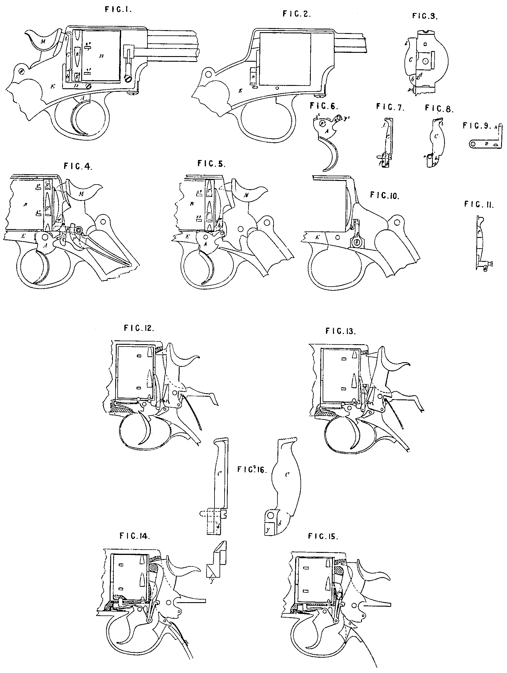
Figure 1 represents a side elevation of the revolver which shows the gate or moveable shield at the rear of the cylinder, with a spring on the exterior of the revolver acting on the said gate.
Figure 2 is a view of the exterior of the revolver, the lock, cylinder, gate, and spring having. been removed, showing an opening in the frame or body of the revolver through which the prolongation or extension of the gate acts.
Figure 3 is a sectional view showing part of the frame or body of the rear of the cylinder, the gate being attached.
Figure 4 is a side elevation of the revolver with the lock exposed, showing all the parts in their respective places, the hammer resting in its normal position.
Figure 5 is a similar view of the same revolver, showing the prolongation of the gate acting on the hammer and through its medium on the, trigger, the other parts of the lock having been removed.
Figure 6 is a side elevation of the trigger.
Figures 7 and 8 are views of the door, gate, moveable shield, or hinged covering-plate.
Fig. 9 is a plan, showing the inner face of the gate spring.
A indicates the trigger; B, the cylinder; C, the door, gate, moveable shield, or hinged covering-plate b, the prolongation, extension, or tail piece of the gate or moveable shield; D, the gatespring; E; the main frame or body; H, the central lever; M, the hammer; O, the pawl or. lifter; P, the lockspring.
The mainframe E is provided with an opening a, shown in Figure 2, to receive the prolongation or, tailpiece b of the gate C.A hole is formed in the mainframe E at d to receive a screw, shown in Figure 8, the said screw being made partly with a smooth surface to serve as a pivot or axle for the gate C.
The gate C is perforated at e, shown in Figure 8, for its pivot or axle, shewn in Figure 7. The said pivot or axle enters the mainframe E at d, passes through the, hole e of the gate C, and into the mainframe E at the rear of the gate C, and is then screwed firmly into the mainframe E at d.
The gate C is constructed with a prolongation or tailpiece b, and is provided with a shoulder, upon the two sides f¹ and f² of which the gatespring D acts.
The gatespring D is of the shape illustrated, and is fastened by means of a screw to the exterior of the revolver, as shown in Figure 1, and the end h of the gate-spring D, shown in Figure 9, acts on the side f? of the shoulder of the gate C in order to keep the gate C in its normal position, covering the rear of the cylinder, and acta also on the side f¹ of the shoulder of the gate C when the gate C is operated on in order to gain access to the rear of the cylinder.
The cylinder. B is of the usual form, and is provided with two series of notches or grooves, the one series indicated by S¹, and the other by S², in Figures 1; 4, and 5, adapted to engage respectively with the lugs or stops i¹ and i² of the trigger A.
The trigger A is of the shape shown in Fig. 6, perforated at g¹ for its pivot or axle, and at g² to receive the pivot of the lifter O. The projection is formed with a tooth to engage with the notch on the projection of the forward side of the hammer.
The trigger Ai s provided on its upper surface with a lug or stop i¹ which enters one of a series of notches S¹ on the cylinder when the weapon is full cocked, and is likewise provided on its upper surface at its front head with a lug or stop i², which when the trigger returns to its normal position after the weapon has been fired enters one of a series of notches S² on the cylinder. The hammer M, the lockspring P, the central lever H, and the pawl or lifter O do not differ from the hammer, mainspring, central lever, and pawl described in my Letters Patent, No. 4302, dated Twenty first October, 1880.
The operation is as follows:—
On operating the hammer or trigger for the purpose of cocking the weapon, the trigger turns on its pivot, and by this movement the lug or stop i² of the trigger A is withdrawn from the notch S² of the cylinder, permitting the lifter O to rotate the cylinder until! a fresh cartridge is brought in a line with the barrel, when the hammer being at full cock the lug or stop i¹ enters one of the series of notches S¹ on the cylinder. The trigger being pulled or retracted, the hammer falls. Upon releasing the trigger the pressure of the lock spring P delivered through the medium of the central lever H and the lifter O carries the projection x of the trigger downward, causing the trigger to turn on its pivot until it resumes its normal position, and by this movement the lug or stop i¹ of the trigger A is disengaged from the cylinder, and the lug or stop i² of the trigger A enters one of the series of notches S² on the cylinder and securely locks the cylinder. To permit the empty cartridges to be extracted or to load the cylinder, it is necessary to liberate the cylinder, to effect which one has only to perform the usual act of opening the gate or moveable shield at the rear of the cylinder; thus, on pushing outwards the summit t of the gate C it turns on its pivot, and by this action the prolongation or tail piece b of the gate C ascends, and the side f³ of the prolongation b of the gate coming under the projection W of the hammer M raises the hammer, and through the medium of the hammer raises the projection x of the trigger A, thereby turning the trigger A on its pivot until the lug or stop i² of the trigger A is disengaged from the notch S² on the cylinder, thus permitting the cylinder to turn freely in order that the cartridges may be extracted or the cylinder loaded. In this position the prolongation b of the gate C, being above and near to the projection x of the-trigger A, impedes any movement of the trigger, and consequently the hammer is unable to act; and there can be no danger of a discharge of cartridge whilst the gate or moveable shield remains open.
On pushing outwards the summit t of the gate C the gate spring D engages with the side f¹ of the shoulder of the prolongation b of the gate, and when the gate C is open to its full extent it is held by the gatespring D securely in this position. On pushing back the gate C to its normal position at the rear of the cylinder the gatespring D engages with the side f² of the shoulder of the prolongation b of the gate C,and holds the gate in position. By the action of the gate C in returning to its normal position, the side f³ of the prolongation b of the gate disengages from the projection W of the hammer, and the prolongation b resumes its place in the opening a of the main frame E flush with the interior of the main frame, the hammer M being disengaged from the prolongation b of the gate. The lockspring P, acting on the central lever H, causes all the parts of the lock to return to their normal position.
I may modify the arrangement I have immediately above described, as shewn in Figures 10 and 11, in which it will be seen that the gate C with its axle or pivot is of one piece; in this case the opening a in the main frame E is dispensed with, the axle or pivot of the gate C entering in a hole in the main frame E at the rear of the cylinder, the axle being kept in its place by a spring in the interior of the main frame E which engages with the sides of the shoulder formed at the extremity of the axle of the gate. In this modification the tail piece of the gate C is detached, and is screwed into the axle of the gate C after it has been fixed in the main frame E. In applying my mode of freeing the cylinder by the action of the gate to ordinary locks, such for example as shewn in Figures 12 to 15 inclusive, in which, the hammers have not the projecting piece w of the arrangement first described, I modify the gate C by forming on the prolongation b thereof an inclined plane tapering to the front, as shewn y, Figure 16, the object of this tapering being that when the gate C is operated the prolongation may lift the hammer and liberate the cylinder, as shown, Figures 13 and 15. The modified gate C is shewn detached and drawn to an enlarged scale at Figure 16. The Figures 12 and 14 shew the locks when not operated by the gate.
I may also modify the arrangement of freeing the cylinder in other ways than those above described, as for instance, the cylinder may be locked with an arm attached to the trigger, as shewn in Figure 14, and this arm may be projected also. in an opposite direction, and the prolongation of the gate may be arranged to operate direct on the rear end of the said locking arm. Or if an arm on the trigger be made to operate a locking device on the rear part of the cylinder the gate or movable shield may be so arranged as to act direct on the said locking device for the purposes of liberating the cylinder.
I may also modify the gate so that it may operate direct on the trigger to free. the cylinder.
Having now described and ascertained the nature of my said Invention, and in what manner the same is or may be performed, I would have it distinctly understood that I do not limit myself to the precise details hereinbefore set forth and shewn in the Drawings as such may be greatly modified while retaining the essential feature of my Invention, namely, the utilization of the door for the purposes specified; and what
I claim as secured to me by the hereinbefore in part recited Letters Patent is,—
First. In a revolving fire-arm, the employment of the door, gate, shield, or covering-plate for effecting the freeing or liberating of the cylinder, for the purposes specified.
Second. In a revolving fire-arm, the use of a door, gate, shield, or covering-plate having a prolongation, extension, or tail piece, arranged to operate substantially as hereinbefore described and shewn on the accompanying Sheet of Drawings.
In witness whereof, I, the said Michael Kaufmann, have hereunto set my hand and seal, this Ninth day of March, in the year of-our Lord One thousand eight hundred and eighty two.
MICHAEL KAUFMANN, (L.S.)