
US 308183
UNITED STATES PATENT OFFICE.
JOHN M. MARLIN, OF NEW HAVEN, CONNECTICUT.
REVOLVER.
SPECIFICATION forming part of Letters Patent No. 308,183, dated November 8, 1884.
Application filed September 13, 1884. (No model.)
To all whom it may concern:
Be it known that I, JOHN M. MARLIN, of New Haven, in the county of New Haven and State of Connecticut, have invented a new and useful Improvement in Fire-Arms, of which the following is a specification.
My invention relates to revolving fire-arms; and it consists in certain improvements in the mechanism for locking the cylinder in position during the operation of firing the arm, substantially as hereinafter described and claimed.
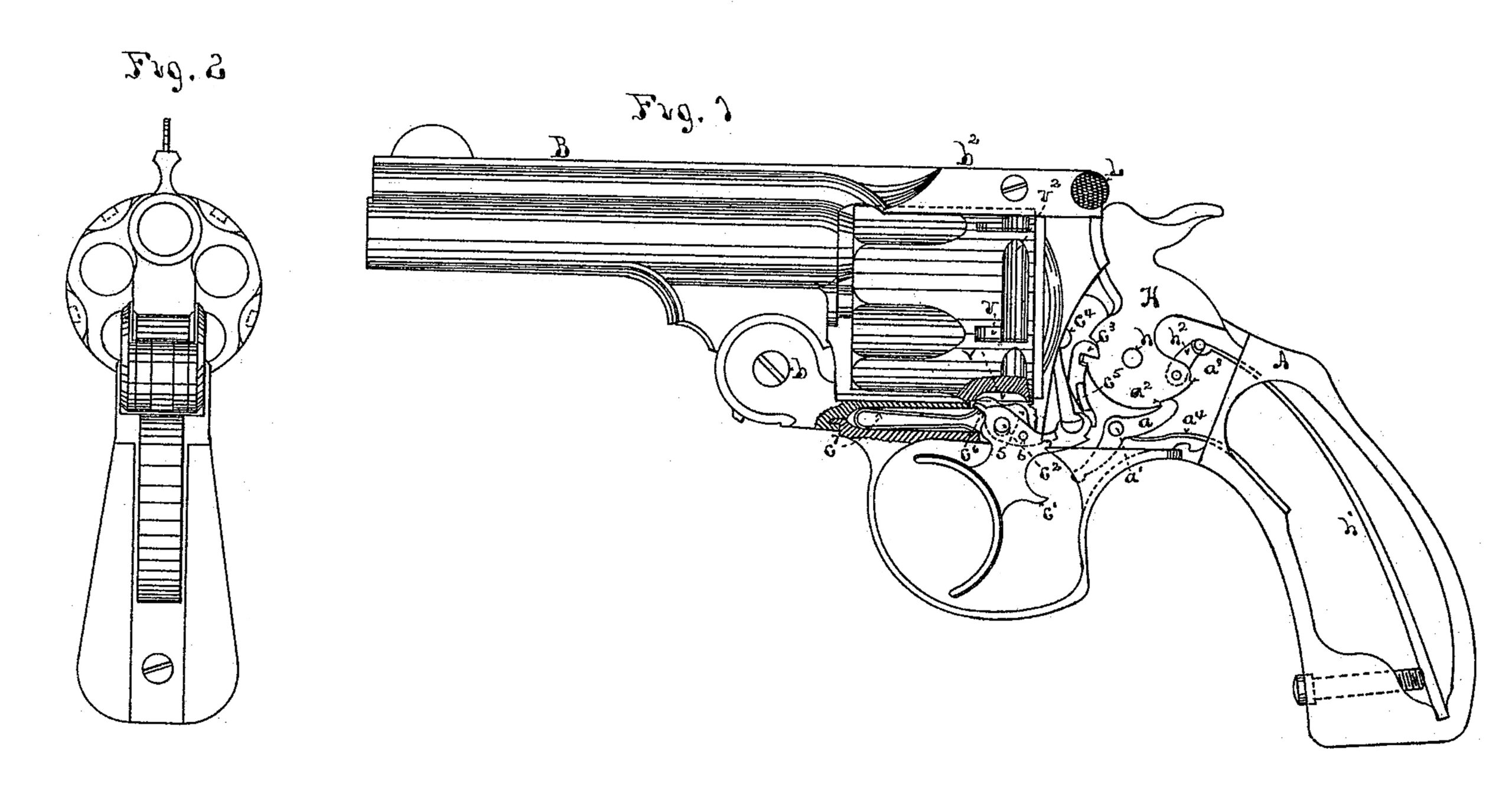
In the drawings, Figure 1 is a side view of a revolving fire-arm with the lock-plate removed, and partly in section, provided with my improvements. Fig. 2 is a front view of the arm looking into the barrel.
A is the frame of the arm; B is the barrel, which is pivoted to the frame in the ordinary manner at b. L is the latch which locks the extension b2 of the barrel to the frame on top. H is the hammer turning on the pivot h. A latch, a, pivoted at a’, engages by a hook on its end with notches a2 a3 on the hammer to hold it in place when cocked, the notch a2 being the safety or half-cock notch, and the notch at the firing or full-cock notch. This latch is held against the hammer and caused to engage with the notches a2 a3 by the spring a4. The hammer-spring h’ is connected to the hammer by the pivoted link h2. A nose, c’, on the trigger c, engages with the free end of the latch a when the trigger is pulled back, and raises this end of the latch, drawing the hook on its opposite end downward out of the notch a3 and firing the arm. This mechanism is designed to operate when the hammer is cocked by hand in the ordinary way. The trigger is pivoted to the frame by the pivot c2. Upon a backward extension of the trigger is pivoted the hooked pawl c3, which engages with notches on the front side of the hammer to raise the hammer and release it automatically to fire the arm when the trigger is pulled back without cocking the hammer by hand. A pawl, c4, is also pivoted to the same extension of the trigger, and has its upper end projecting through the recoil-shield, and it engages with the notches in the rear end of the cylinder and revolves it in the usual man her when the trigger is drawn backward. A spring, c5, attached to this pawl and bearing against the hooked pawl c3, keeps both pawls in position to operate. All of these parts are well known and operate in the ordinary manner.
In order to lock the cylinder in place I have devised the following mechanism: In the upper edge of the trigger c I form a mortise to some distance below the pivot c2, and in this mortise I place a piece of metal, 5, which is of a proper thickness to slide easily up and down in the mortise, and is pivoted therein at 6 by a pivot passing through the trigger. The piece of metal 5 has a hole transversely through it where the axis of the trigger c2 passes through it, which hole is made considerably larger than this axis, as shown in dotted lines in Fig. 1, so as to allow piece 5 to play up and down in the mortise, turning on its pivot 6. The contour of the lower edge of piece 5 is indicated in dotted lines in Fig. 1. The trigger has on its forward side a projecting part, c6, through which the mortise from its upper side passes entirely, and the trigger is held forward by a spring, c7, which has its upper end as broad as the transverse thickness of the trigger, and bearing under projection c6. The piece 5 extends through the mortise, where it passes through projection c6, and consequently the spring c7 bears against it as well as c6, and holds it upward in the mortise in the trigger at the same time that it holds the trigger forward. The piece 5 has on its upper end a double nose projecting above the upper edge of the trigger in such a position that when the trigger is forward, the forward member of said double nose shall engage with the notches v v in the cylinder, and when the trigger is drawn back to its limit the other member shall engage with said notches; but as the trigger is passing from its forward to its rearward position both members of said nose shall be withdrawn from said notches and allow the cylinder to revolve. The spring c7 serves to hold both members of the nose of piece 5 upward with an elastic pressure, which allows for any slight irregularity in the rotation of the cylinder.
In order to permit the cylinder to revolve freely as the trigger is drawn back without the rearward member of the nose on piece 5 bearing against it, circumferential grooves v2 v2 are made in the surface of the cylinder terminating in the notches v v. These grooves v2 allow the cylinder to revolve freely until the rearward nose brings up in the notches v v.
I am aware that a double stop attached by a pivot in the trigger has been used heretofore in revolving fire-arms with a cylinder having two rows of stop-notches for said double-stop to act with; but my device is essentially different from that in having the double nose which forms the two members of the stop on the same side of the pivot upon which the stop is hung, instead of on both sides of it; and, further, in being provided with an enlarged hole about the pivot c2 on which the trigger swings, so as to move up and down past the latter pivot. This construction enables me to employ but one spring to give an elasticity to both members of the nose of the double stop instead of two springs, one for each member of the nose, as heretofore. I am also enabled by my construction to employ but one set of stop-notches, v, in the cylinder, because the pivot 6 of the stop is so placed as to give the necessary elasticity to the stops while they lie close together without that degree of circular movement which would occur if they were as near together when placed on opposite sides of the stop-pivot, as heretofore. This renders the cylinder neater in appearance than when provided with two rows of stop-notches.
What I claim as new and of my invention is–
The combination of the cylinder provided with stop-notches v v , the trigger provided with the double-nose stop-piece 5, pivoted to the trigger on one side of its double nose, and the spring c7, substantially as described.
JOHN M. MARLIN.
Witnesses:
C. F. DEMMER,
CHARLES DALY.