
US 250591
UNITED STATES PATENT OFFICE.
DEXTER SMITH, OF SPRINGFIELD, MASSACHUSETTS.
REVOLVING FIRE-ARM.
SPECIFICATION forming part of Letters Patent No. 250,591, dated December 6, 1881.
Application filed October 15, 1881. (No model.)
To all whom it may concern:
Be it known that I, DEXTER SMITH, a citizen of the United States, residing at Springfield, in the county of Hampden and State of Massachusetts, have invented new and useful Improvements in Revolving Fire-Arms, of which the following is a specification.
This invention relates to revolving fire-arms, and more particularly to certain parts of the extractor devices thereof, the object being to effect a positive locking of the extractor-stem to the frame of the arm by the movement of the hammer, which explodes the cartridge, and whereby said extractor-stem is held while the cylinder is drawn forward to extract the empty shells therefrom.
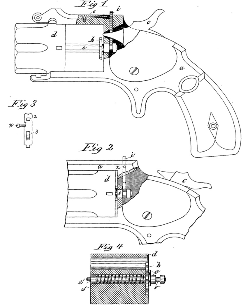
In the drawings forming part of this specification, Figure 1 is a side elevation, partly in section, of the frame and cylinder of a revolving fire-arm embodying my improvements. Fig. 2 is a side elevation of the central portion, partly in section, of a fire-arm, showing the hammer cocked. Fig. 3 is a side elevation of the extractor-stem bolt. Fig. 4 is a longitudinal section of the cylinder, showing the extractor, the extractor-stem and the extractor-spring in full lines.
In the drawings, a is the frame of the arm; d is the cylinder. b is the extractor. c is the extractor-stem. s is the extractor-spring. i is the extractor-stem bolt. o is the bolt-spring. x is a stop-screw. c is the hammer. c’ is the front cylinder-pivot.
The general construction of this arm is that of arms of this class, or those in which the barrel is hinged to the frame above and at the front end of the cylinder, the latter being adapted to slide forward on the extractor-stem to extract the shells. The lock of the arm is of common construction, excepting that the nose of the hammer is peculiarly formed to adapt it to the improvements which are the subject of this application.
The portion of the extractor-stem e which is directly connected to the extractor b, and which extends nearly through the cylinder, is of the usual octagon form; but to its front end is screwed the cylindrical front pivot, e’,on which, within the cylinder, is formed a shoulder or abutment, against which the forward end of the spring s bears, to draw the extractor b against the rear end of the cylinder, while the rear end of said spring is forced against the rear end of the extractor-stem chamber in the cylinder. Said pivot e’ fits said chamber and slides easily therein. The rear end of the extractor-stem e, or that portion thereof which forms the bearing for the rear end of the cylinder, and which projects rearwardly beyond the recoil-shield of the arm, has a groove, v, formed in it.
In frame a is fitted a vertically-sliding extractor-stem bolt, i, whose lower end is adapted to engage in the groove v in said extractor-stem, and whose upper end projects above frame a over the cylinder, and serves as a rear sight for the arm. Said bolt i,. has two transverse perforations, 2 and 3. In the upper side of said frame, over the cylinder, is located a spring, o, whose free end engages in the perforation 2 in bolt i. A stop-screw, x, is inserted through the side of frame a into a slot or notch in the edge of bolt i, and prevents undue movement of said bolt. The perforation 3 through bolt i is, when said bolt is in the frame, as shown in Fig. 2; in such position that the nose of the hammer c will pass through it when the arm is fired, or when the hammer swings over to strike the cartridge, and as the hammer-nose passes through said perforation in bolt c, the lower edge of said nose strikes the lower side of said perforation, and drives the bolt down, making its lower end enter groove v in the extractor-stem, and so long as the hammer-nose is in this position said stem is effectually locked to the frame, but by partially or fully cocking the hammer the bolt i is so far freed from the latter as to allow spring o to draw it up and out of said groove in stem e.
From the foregoing description it will be easily understood that the extractor-stem and extractor are firmly locked against any forward movement while the nose of the hammer is in the position shown in Fig. 1, and that therefore the cylinder can be drawn forward in the frame and upon stem e away from the extractor b, causing the shells to be withdrawn from the cylinder.
When the cylinder is withdrawn, as above described, spring s is compressed between said abutment on the front pivot, c’, and the opposite end of the extractor-stem chamber, and if hammer c be cocked while the cylinder is so withdrawn, the extractor and stem will immediately shoot away from the frame and assume the position in which they are in Fig. 4; or, if the cylinder be released after having been drawn out, as in Fig. 1, spring s will draw it rearward against the extractor and toward the recoil-shield of the arm.
What I claim as my invention is—
1. In combination with an extractor-catch located in the rear of the recoil-shield and arranged to hold the extractor while the cylinder is being moved forward to extract the empty shells, the cylinder, extractor, and extractor-spring having suitable stops and abutments, the combination being and operated substantially as set forth.
2. In combination with the extractor-stem e, having an annular groove around the end thereof in the rear of the recoil-shield, the bolt i, set vertically in the frame a, in the rear of the recoil-shield, and provided with the perforation 3, to admit of the passage therethrough of the nose of the hammer, and hammer c, substantially as set forth.
DEXTER SMITH.
Witnesses:
H. A. CHAPIN,
J.D. GARFIELD.