
US 246940
UNITED STATES PATENT OFFICE.
HOMER M. CALDWELL, OF WORCESTER, ASSIGNOR OF ONE-HALF TO DEXTER SMITH, OF SPRINGFIELD, MASSACHUSETTS.
REVOLVING FIRE-ARM.
SPECIFICATION forming part of Letters Patent No. 246,940, dated September 13, 1881. Application filed July 21, 1881. (No model.)
To all whom it may concern:
Be it known that I, HOMER M. CALDWELL, a citizen of the United States, residing at Worcester, in the county of Worcester and State of Massachusetts, have invented new and useful Improvements in Revolving Fire-Arms, of which the following is a specification.
This invention relates to the details of the construction of cylinder-stop mechanism for revolving fire-arms, the object being to provide an improved cylinder-stop, whereby the cylinder will be held positively, so that it cannot be revolved, and the ends of the cartridges displaced relative to the line of the barrel and the hammer.
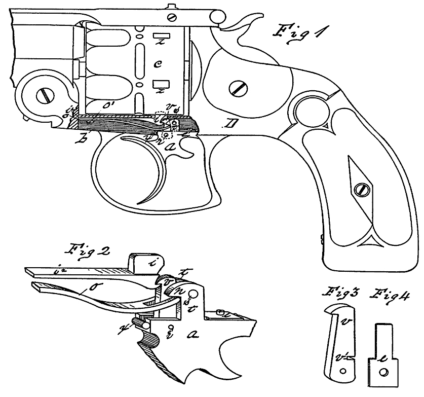
In the drawings forming part of this specification, Figure 1 is a side elevation, partly in section, of a revolving fire-arm, the forward part of the barrel being broken away, embodying my invention. Fig. 2 is a view of the cylinder-stop and its operating parts, enlarged and separate from the arm. Figs. 3 and 4 represent, respectively, the stop-latch and its operating- spring, also enlarged and detached from the arm.
In the drawings, D represents the frame of the arm here shown, which arm represents, substantially, an ordinary self-cocking or double-action pistol excepting the improvements herein shown, which are the subject of this application, and which are adapted to the above- named class of arms. The arm of the frame D, which extends under the cylinder, is represented by the letter b. c is the cylinder. a is the trigger. n n are spring-hooks on trigger a. o is the trigger-spring. v is the stop latch. e is the stop-latch spring.
The cylinder c is made with the usual stop indentations, z, in its surface. The arm b of the frame D is chambered on its under side longitudinally, to receive the cylinder-stop and the trigger-spring and the stop-operating parts of the trigger, as hereinafter more fully set forth, and is perforated between said chamber and the cylinder, to allow the end of the cylinder-stop to pass up through and engage with the cylinder in the usual way.
The trigger a has two posts, t t, standing on its upper edge, which project up into said chamber in the arm b of the frame, and the trigger swings on a pin, s, which passes transversely through the upper parts of said posts and through the sides of said chamber. The connection of the rear part of the trigger with the operative parts of the arm In the frame D, behind the cylinder, is of the usual description in the aforesaid class of pistols. A cut is made in the upper edge of said trigger, to allow of placing the stop-latch v vertically therein, and there pivoting it by the pin r, so that it can vibrate between the posts t t, and the end of a spring, e, whose free end engages in a transverse cut, v’, in said latch, is secured upon the top edge of the trigger, and its narrow end reaches forward between the posts t t, for the purpose just stated, and said spring operates to throw the upper end of said latch in the direction of the hook on its edge opposite to said spring. Each of said posts t t is provided with a spring-hook, n, under which the end of the trigger-spring o, which is slotted, as shown, to clear the latch v, engages.
The cylinder-stop i is made with a spring shank, i2, running forward in said chamber in arm b, through which, near its end, a screw, o’, passes, fastening it to the roof of said chamber, and upon the end of said stop next to the hook on the latch v is cut a notch, in which said hook engages. The trigger-spring o, as well as said spring-shank of the stop i, is se- cured in said chamber in arm b by said screw o’. A pin, x, is put through arm b near the forward edge of the trigger a, which prevents the latter from being thrown too far by the spring o. Any other suitable trigger-stop may be substituted for said pin.
The operation of my improvements is as follows: When the stop i is undisturbed by any motion of the trigger the spring of its shank will hold it positively in engagement with one of the stop-cavities z on cylinder c. When the trigger is pulled to cock the arm, latch v draws down stop i away from the cylinder, holding said stop down until said cylinder has revolved to bring the cartridge-chamber therein nearly in a line with the barrel, and just before the hammer falls stop i slips off from the latch v and springs up and stops the cylinder, and there remains while the trigger, actuated by spring o, swings forward, and latch v, actuated by spring e, re-engages with it, thereby making a positive cylinder-stop for this class of arms. The stop andits operating devices are now in a position for a repetition of the aforesaid operations.
I am aware that it is not new in revolving fire-arms to pivot a cylinder-stop in that part of the frame under the cylinder adapted to lock the cylinder when the arm is fired, and I do not broadly claim such construction; but
What I claim as my invention is—
1. The combination, with the cylinder-stop a and with the trigger a, of the latch v, pivoted in said trigger, and spring c, substantially as set forth.
2. The combination, in a revolving fire-arm, of the cylinder c, the stop i, the trigger a, having the posts t t, with hooks n thereon, spring o, the latch v, pivoted in said trigger, and spring e, substantially as set forth.
HOMER M. CALDWELL.
Witnesses:
M. J. MCCAFFERTY,
DEXTER SMITH