
US 212606
UNITED STATES PATENT OFFICE.
IVER JOHNSON AND MARTIN BYE, OF WORCESTER, MASSACHUSETTS.
IMPROVEMENT IN REVOLVING FIRE-ARMS.
Specification forming part of Letters Patent No. 212,606, dated February 25, 1879; application filed December 6, 1878.
To all whom it may concern:
Be it known that we, IVER JOHNSON and MARTIN BYE, both of the city and county of Worcester, State of Massachusetts, have invented certain new and useful Improvements in Fire-Arms, of which the following is a specification:
Our invention is designed to simplify the construction and secure certainty of action, and, though applicable to many kinds of fire-arms, is more particularly so as an improvement on the invention patented by us on June 4, 1878, No. 204,438. Its nature is shown in the following description and accompanying drawings, in which–
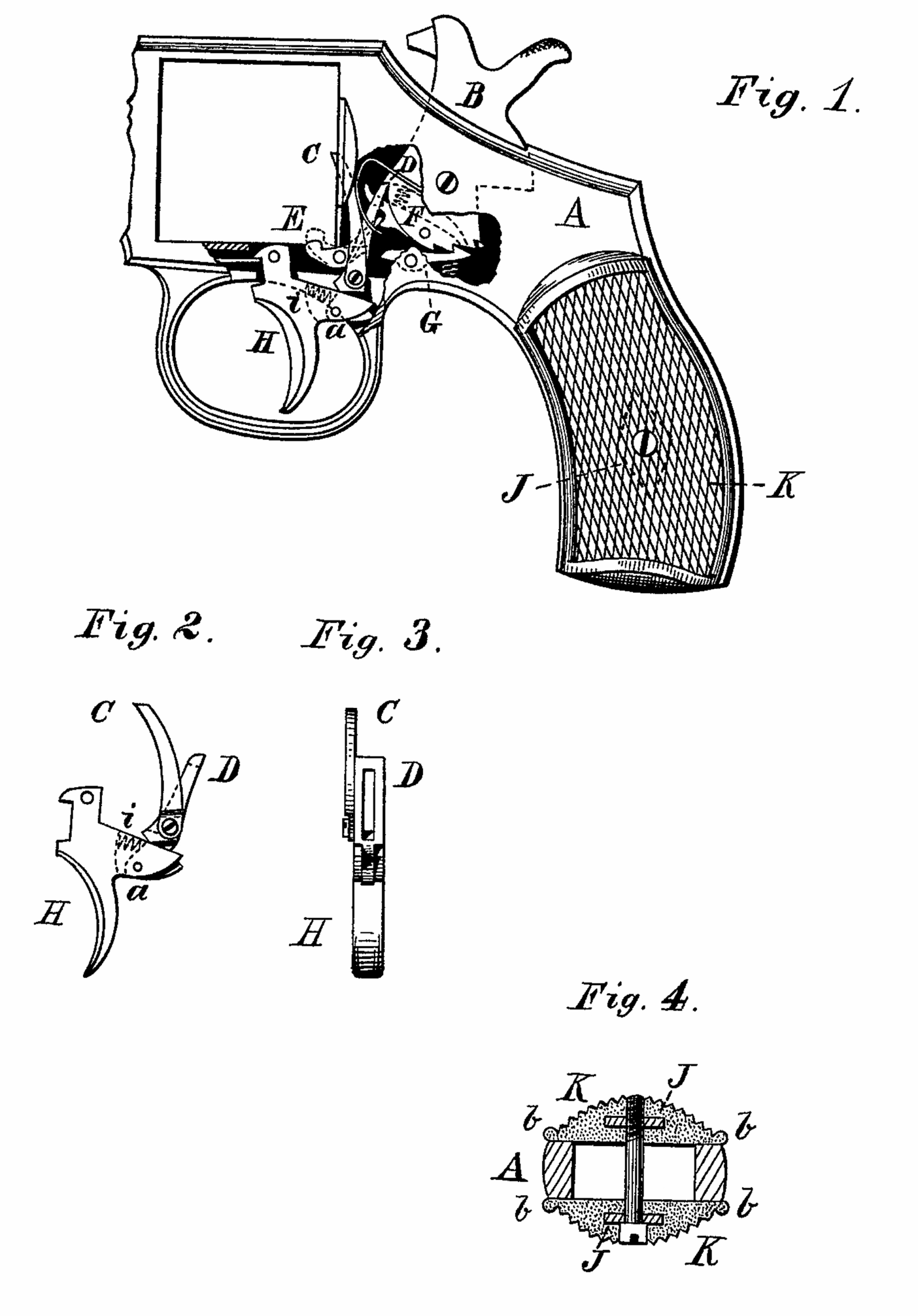
Figure 1 shows a side view of a revolver embodying our invention. Figs. 2 and 3 show two views of the trigger H and levers C and D. Fig. 4 shows a cross-section of the frame and sides of the handle.
The same letters indicate the same parts wherever they occur.
The parts not shown may be of most any of the common forms.
In the construction of double-acting revolvers as heretofore made great difficulty has been found in controlling the motion of the cylinder by an efficient stop. We accomplish this by extending the rear end of the stop lever and having a lever, pivoted to the hammer in such a manner that the first motion of the hammer shall relieve the stop, allowing the cylinder to commence its motion, and the further motion of the hammer frees its lever from the stop-lever, allowing the latter to be thrown against the cylinder ready for action, securing the stopping of the cylinder at the right time, and the action of these parts is the same whether the piece is fired by the trigger as a self-cocker or by first cocking by the hammer.
In the drawings, A is the frame; B, the hammer; C, a pawl pivoted to the pawl D, and giving motion to the cylinder. The pawl D is pivoted to the trigger H, and has a slot, as shown in Fig. 3, through which the curved end of the lever F passes, and whereby said lever draws back the trigger H when the piece is cocked by the hammer. The upper end of D acts on a notch in the hammer to fire the piece by pulling the trigger. The lever F is pivoted to the hammer B in such a manner that its curved forward end performs the aforesaid function, while a notch on its under side or surface acts to tilt up the rear end of the stop-lever E at the proper time to release the cylinder for the pawl C to turn it, and passes said lever E, allowing its front end to be pressed up against the cylinder in ample time to stop its motion.
In fitting the sides K K to the handle, we make the frame as shown at A, Fig. 4, and the sides with a projecting edge or edges, thereby forming ribs in the outline of the handle, which aid the hand in holding it steadily and firmly, and saving the necessity of the accurate fitting of the edge of the side to the adjacent corner of the frame, which, as heretofore made, required the services of a skilled workman and took considerable time.
The sides K. K., which are usually made of hard rubber or other composition, are formed in molds with a press, in which we embed a collar and nut, J J, below the surface, so that the outside finish of said sides can be perfected without reference to them, they superseding the necessity of using the escutcheons as heretofore inserted. The collar under the head can be threaded and the screw made to correspond, if desired. This construction enables us to finish the surfaces of K K in the press in any ornamental manner desired up to and surrounding the aperture for the screw, or, in other words, so as to require no additional finish for escutcheons, as heretofore necessary. The projecting ribs b b allow the sides to shrink without affecting their fit.
What we claim as new, and desire to secure by Letters Patent, is–
1. The combination, in a double-acting revolver, of the stop-lever E and a relieving lever, F, pivoted to the hammer, substantially in the manner and for the purposes above set forth and described.
2. The combination of the projecting sides forming a rib or ribs at their edge with the frame A, substantially as described.
3. The side pieces K. K., having the collar and nut embedded therein, so as to be below the surface and still furnish bearings for the screw, substantially as described.
In testimony whereof we have hereunto set our hands in the presence of two witnesses.
IVER JOHNSON,
MARTIN BYE.
Witnesses:
EDWARD K. HILL,
J. G. ARNOLD.