
US 202418
UNITED STATES PATENT OFFICE.
AMÉDÉE THORNTON DE MOUNCIE, OF LONDON, ENGLAND, ASSIGNOR OF ONE-FOURTH OF HIS RIGHT TO MICHAEL KAUFMANN, OF SAME PLACE.
IMPROVEMENT IN LOCKS FOR FIRE-ARMS.
Specification forming part of Letters Patent No. 202,418, dated April 16, 1878; application filed November 27, 1877.
To all whom it may concern:
Be it known that I, Baron AMÉDÉE THORNTON DE MOUNCIE, of London, England, have invented certain new and useful Improvements in Fire-Arms; and I do hereby declare the same to be fully, clearly, and exactly described as follows, reference being had to the accompanying drawings, in which—
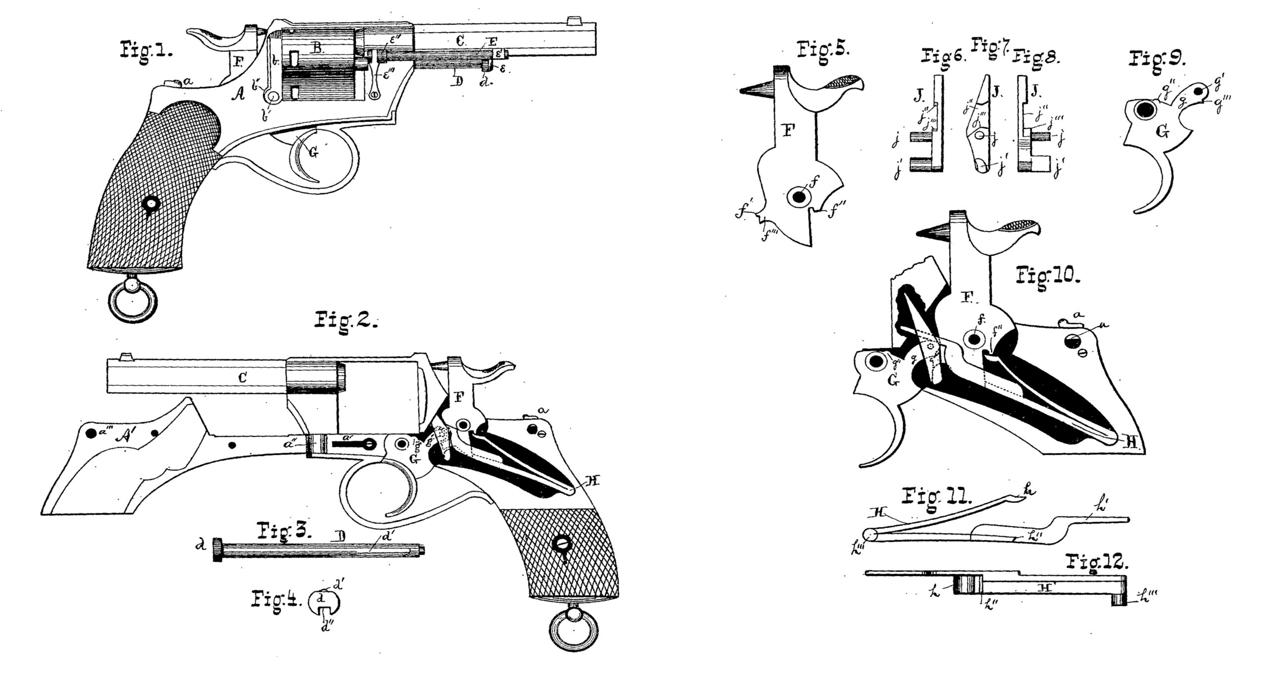
Figure 1 represents a side elevation of a revolver embodying my present improvements; Fig. 2, a similar view, the cover of the lock being laid back in order to illustrate the lock mechanism. Figs. 3 and 4 are, respectively, plan and end views of the cylinder-pin. Fig. 5 is a side elevation of the hammer. Figs. 6, 7, and 8 are, respectively, front, side, and rear elevations of the pawl; Fig. 9, a side elevation of the trigger. Fig. 10 is an enlarged view of the lock complete; and Figs. 11 and 12, respectively, a side elevation and bottom plan of the mainspring.
While in the accompanying drawings I have illustrated my invention as embodied in a revolving pistol, it is by no means limited thereto, certain salient features of the said invention being equally applicable to and valuable in any variety of percussion fire-arm, as will be readily understood from the following description.
In the drawings, A represents the main frame of the weapon, provided with studs or pivots for the hammer and trigger, and having a cover-plate, A’, hinged at its forward end. The plate A’ carries a stud, a’’’, which enters a corresponding hole in the main frame when the cover-plate is closed, and is there secured by a spring-latch, a. The plate A’ is. also provided with holes, as shown, into which the trigger and hammer pivots enter when the plate is closed. In order to open it for access to the lock, the latch a is raised, when a spring, a’, causes the cover-plate to fly open.
The cylinder B and barrel C are of the ordinary construction, except that the notches in the former for the latching-detent have a gradually-entering groove, as shown—a construction rendered necessary from the fact that the detent g” upon the trigger has a positive and gradual upward motion pending the revolution of the cylinder.
The cylinder-pin D (see Figs. 3 and 4) is provided with a side spring, d’, at the part which is normally within the cylinder, in order to prevent a too free revolution of the same. The head d is slotted, as shown at d”, the said slot serving to secure the mainspring when it is desired to take the lock to pieces, as hereinafter described.
The device for retracting the exploded cartridge-shells is illustrated in Fig. 1, and consists of a tube, E, which slides freely upon a rod and through a tubular bearing, e’’, secured to the main frame A, the rod referred to being attached, at e’, to the barrel C. The tube E is provided with a head, e, which normally covers the end of the cylinder-rod D, preventing its accidental retraction. The tube E is slightly flattened on the side which comes next the frame A when the head e is in place over the end of the cylinder-rod, being retained in position by means of the spring e’’’.
An arm, b, pivoted to the main frame at b’ at the rear of the cylinder, and held in place by means of a spring, b”, serves to prevent the cartridges from falling out of the cylinder, and when it is thrown back free access is afforded to the cylinder for the insertion or removal of cartridges or retraction of empty shells.
Such is a brief description of the external parts of the weapon. The lock, which forms the gist of my present improvement, will be described more in detail, the parts being taken up seriatim.
The hammer F is provided with the ordinary point for exploding the cartridge, and roughened thumb-piece. A hole is formed in it for the central pivot at f, and on the rear side of the hammer is formed a bearing, f”, for the mainspring. On the forward side of the hammer is a projection, f’’’, having a notch for engagement with the trigger when the hammer is thrown back, the said projection serving also as a means for effecting the so-called “‘self-cocking” of the weapon, as will be hereinafter set forth. J represents the cylinder-pawl, (see Figs. 6, 7, 8,) which consists of a flat steel bar, countersunk on one side, as shown at j”, and provided with a pivot, j, and lug j’. The lower portion or bottom of the countersunk part j” consists of two planes, inclined as shown, and meeting in a point, j/, forward. of the pivot J, the object of which construction will be presently evident.
The trigger G is of the shape illustrated, and is perforated for the insertion of the pivot. A small lug, g”, is formed on the upper surface of the trigger, which enters one of the notches upon the cylinder when the weapon is full-cocked. A projection, g, perforated at g’ for the pawl-pivot, has a notch, g”, adapted to engage with the projection f’ upon the hammer.
The mainspring H consists of two leaves, the one adapted to engage at h with the bearing f” upon the hammer, the other constituting at h’’ a safety-stop for the hammer, and having an arm, h’, which subserves the double function of sear-spring and pawl-spring. The usual lug h’’’ is provided at the junction of the leaves, and is adapted to enter a step in the main frame.
In Fig. 10 the parts of the lock are shown in their proper juxtaposition, the hammer resting in its normal position against the safety-catch.
It will be observed that the projection f’’’ upon the hammer occupies a position between the lug j’ of the pawl and that, g, upon the trigger, fitting snugly between them. The arm h’ of the mainspring rests upon the rear plane of the countersunk portion of the pawl, and holds the latter in. proper position. Upon cocking the weapon by the thumb of the operator, the hammer causes the trigger to rotate about its pivot, carrying with it the pawl, and thereby effecting the rotation of the cylinder, and at the same time bringing the leaves of the mainspring together. Finally, the projection f’ upon the hammer falls into the trigger-notch g’’’, and the weapon is full-cocked. Upon retracting the trigger the hammer is released and fails upon a cartridge. The trigger being now released, the lower leaf of the mainspring falls, and its safety-stop h’’ engages with the lower part of the hammer, which is thereby lifted clear of the cartridge.
Instead of cocking the weapon in the usual manner, it may be used as an ordinary self cocker. The trigger being retracted,the pawl is thereby lifted, and its lug j’, engaging with the under side of the projection f’”, raises the hammer until the engaging parts pass the line joining the pivots, when the hammer is released and fails, the safety-stop subsequently slightly raising it, as just described.
It will have been observed that not a single screw is used in the lock mechanism, affording increased facility for taking the latter apart for cleaning.
To remove the parts of the lock, the cylinder-pin D is removed, and, the weapon being full-cocked, the mainspring is clamped in the slot d’’ in the head of the cylinder. The hammer being now allowed to fall, the mainspring may be lifted out, and then, in order, the pawl, trigger, and hammer. To replace them, they are put in position in reverse order.
As hereinbefore stated, my invention is by no means limited to use in revolving firearms.
Where a cylinder is not used, of course, a pawl would be a superfluity, and as such would be dispensed with, the long leaf of the mainspring being mace, to press directly upon the trigger.
Except in revolvers, the self-cocking feature is not desirable, but might be readily supplied by furnishing the trigger with a swinging link having a lug adapted to engage with the under side of the projection f’’’ upon the hammer.
The salient feature of my invention consists in the rebounding hammer, actuated by the safety-stop upon the mainspring. It affords absolute security against the accidental discharge of the weapon, since the hammer cannot be made to reach a cartridge without either breaking the mainspring or else fullcocking the weapon and then pulling the trigger. In the former case the fall of the hammer would not be sufficient to explode a cartridge, and the chance of the accidental occurrence of the latter is too remote to merit consideration.
Aside from the advantage named above, other and equally important ones flow from the peculiar construction and mutual adaptation of the working parts.
The lock is readily accessible, easily taken to pieces, consisting of but four parts, and those possessing in the highest degree the desirable attributes of strength, simplicity, durability, and effectiveness.
The mainspring alone subserves the functions of sear-spring, pawl-spring, and safety-stop, in addition to its usual function of actuating the hammer, thereby dispensing with parts which have heretofore been necessarily delicate and frail, and liable to get out of repair.
Furthermore, the peculiar disposition of the parts of the lock conduces to greatly-increased facility in operating them. The pressure of the mainspring upon the hammer and trigger is at its maximum at the end of the stroke of the hammer and upon the release of the trigger, the line of thrust of the leaves of the mainspring approaching the pivots of hammer and trigger as the former is raised.
But very slight effort is required to retain the trigger in its retracted position after releasing the hammer, as the leverage of the trigger upon the lower leaf of the mainspring is then at its maximum, and the line of thrust falls very near the trigger-pivot. For these reasons the fall of the hammer is utterly unimpeded by the leaf of the mainspring bearing the safety-catch, which therefore cannot come into gear with the hammer until after its stroke,
Having thus described my invention, what I claim as new, and desire to secure by Letters Patent of the United States, is—
1. In a fire-arm, a mainspring having two leaves, as described, one of which actuates the descent of the hammer, the other having a safety-stop, which is carried, in the act of cocking the weapon, to a position clear of the hammer in its fall, and operating, when the trigger is released, 4o raise the hammer clear of the cartridge, and there securely retain it, as set forth.
2. In a fire-arm, a hammer provided with a tail-piece, in combination with a mainspring having an offset to engage therewith and effect the rebound and locking of the hammer, substantially as described.
3. In a fire-arm, the hammer thereof having a projection or lug engaging with the trigger -as the hammer is raised, and thereby compressing the mainspring, which latter is provided with a safety-stop, which engages with the hammer upon the release of the trigger, substantially as described.
4. In a fire-arm, a trigger adapted to effect the self-cocking of the weapon, in combination with a mainspring provided with a safety-stop, which engages with the hammer upon the release of the trigger, as set forth.
5. In a revolving fire-arm, and in combination with its mainspring, a cylinder-pawl thereby actuated, as described.
6. In a revolving fire-arm, and in combination with its hammer and trigger, a cylinder pawl, constructed as described, and engaging with the hammer upon the retraction of the trigger, and thereby effecting the self-cocking of the weapon, substantially as set forth.
7. In a revolving fire-arm, a lock consisting of hammer, pawl, trigger, and mainspring, the latter provided with a safety-stop for the hammer, and actuating all of the parts named, substantially in the manner and for the purposes set forth.
AMÉDÉE THORNTON DE MOUNCIE.
Witnesses:
JOHN WATT,
JOHN GYNNE.