
US 336021
UNITED STATES PATENT OFFICE.
JOHN T. SMITH, OF ROCKFALL, CONNECTICUT.
LOCK FOR REVOLVERS.
SPECIFICATION forming part of Letters Patent No. 336,021, dated February 9, 1886.
Application filed May 4, 1885. Serial No. 164,299. (No model.)
To all whom it may concern:
Be it known that I, JOHN T. SMITH, of Rockfall, in the county of Middlesex and State of Connecticut, have invented a new Improvement in Revolvers; and I do hereby declare the following, when taken in connection with accompanying drawings and letters of reference marked thereon, to be a full, clear, and exact description of the same, and which said drawings constitute part of this specification, and represent, in-
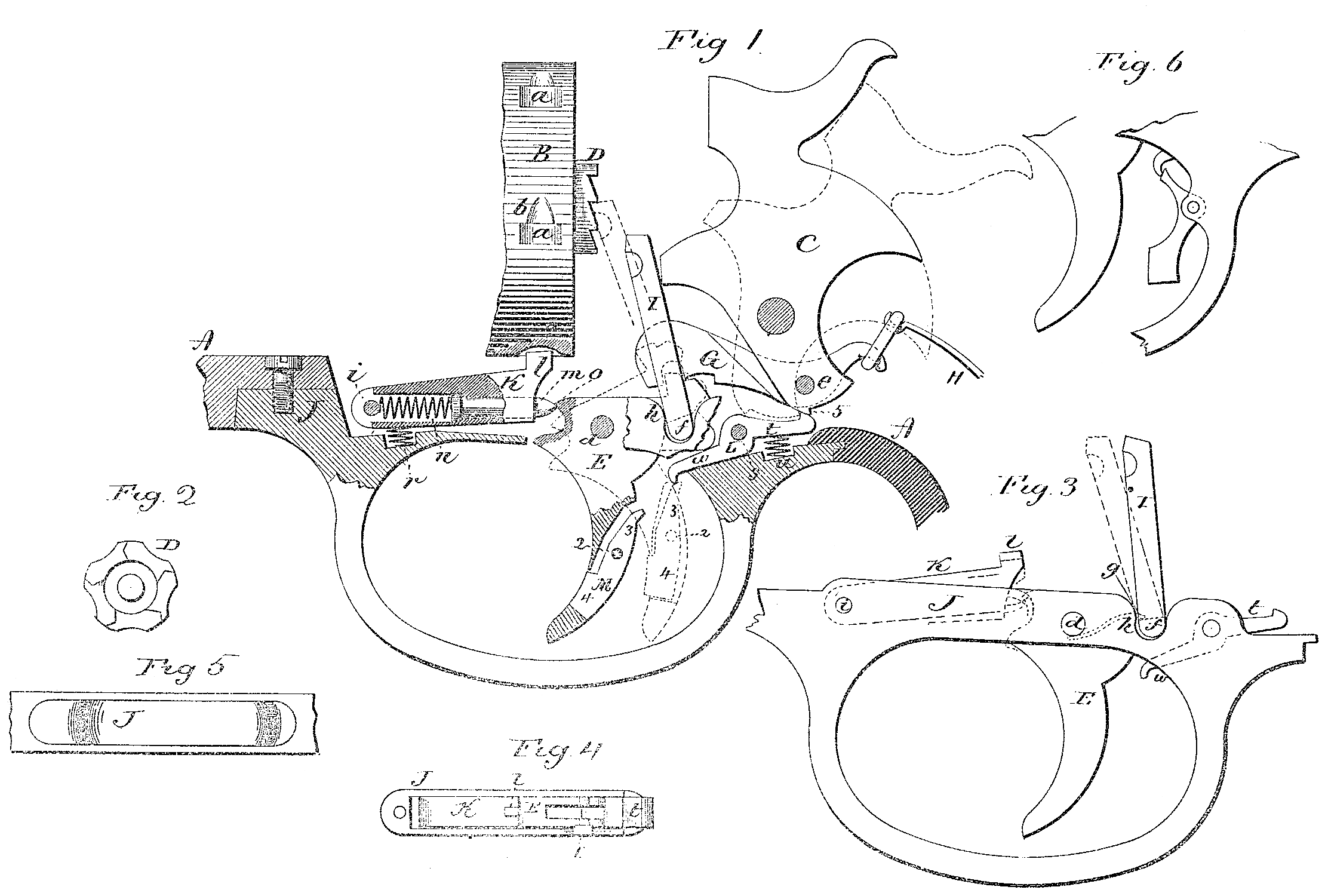
Figure 1 , a sectional side view, showing so much of the revolver as will illustrate my improvement; Fig. 2, a rear view of the cylinder-ratchet; Fig. 3, the trigger-guard plate detached; Fig. 4, a top view of the trigger-guard plate; Fig. 5, an underside view of the trigger-guard plate as inserted in the frame; Fig. 6, a modification in the arrangement of the auxiliary trigger.
This invention relates to an improvement in that class of revolvers which are constructed so that the hammer may be cocked wither by means of the trigger, to be what is called “self-cocking,” or may be cocked by applying the thumb to the hammer only, and in which the cylinder is rotated by a pawl in connection with the trigger. In revolvers thus constructed the first portion of the pull of the trigger, while cocking the hammer, at the same time revolves the cylinder through the pawl, which is hung to the trigger in rear of its pivot, and as the hammer must not be discharged until after the cylinder has been brought to the required position, it follows that there must be a movement to the trigger beyond that which is required to rotate the cylinder; hence the pawl which operates upon the ratchet on the end of the cylinder must escape from the ratchet before the trigger can be pulled – that is, so that the movement if the cylinder may cease before the hammer is discharged. This continued escape of the pawl from the ratchet wears upon the shoulders of the ratchet, as well as the nose of the pawl, so that after a time repairs must be made or the cylinder will not reach its true position with relation to the hammer and barrel. To obviate to a considerable extent this difficulty, more or less play is allowed between the cylinder and the dog which locks it, so that the cylinder is not positively held in its position in line with the barrel.
The principal object of my invention is to provide for a positive and rigid lock for the cylinder when in line with the barrel, and avoid the necessity of the escape of the pawl from the ratchet, whereby the wear before referred to in the previous construction will be obviated; and it consists in the construction of the parts, as hereinafter described, and more particularly recited in the claims.
A represents the frame, which is of usual construction; B, the cylinder, and C the hammer, also of usual construction and arrangement, except as to the ratchet D and locking notches a.
Instead of constructing the locking-notches with a recess gradually opening into them from the advancing side, as indicated in broken lines at b, Fig. 1, I cut a plain square-sided recess, and the ratchet I make simply a plain toothed ratchet, as seen in Fig. 2.
E is the principal trigger, hung upon a pivot, d in the usual manner of hanging a trigger. The trigger is provided with a dog, F, to engage a lever, G, which is hung to the hammer upon a pivot, e, and so that as the trigger is pulled the hammer will be thrown to its cocked position, as indicated in broken lines, and in the usual manner, the mainspring H being connected to the lever G in rear of its pivot, and so that as the trigger is pulled the hammer will be thrown to its full-cocked position, as seen in broken lines, Fig. 1. To the trigger, in rear of its pivot, the pawl I is hung upon its own pivot f. The trigger and the pawl I are both hung in the trigger-guard plate J. The guard-plate is constructed to be introduced into a corresponding recess in the under side of the frame, as seen in Fig. 1, and as shown detached in Fig. 3. In the guard-plate, in rear of the trigger, is a recess, g, into which the lower end of the pawl passes as the trigger is thrown forward. The forward side of this recess is made can-shaped, as at h, and so that as the trigger is thrown forward and the pawl backward it rides over the cam h, and as the pivot of the pawl passes below the said cam h the front side of the pawl will work over the cam h, and thereby thrown back into the position indicated in Figs. 1 and 3; but so soon as the trigger is pulled so far as to carry the pivot of the pawl above the cam h then the spring of the pawl will cause its nose to be thrown forward, as indicated in broken lines, Fig. 3, into engagement with the ratchet, and so that a continued pull of the trigger will cause the pawl to rise and correspondingly turn the cylinder one notch, and when the pawl and cylinder have reached this point the trigger has arrived at its extreme rear position (indicated in broken lines, Fig. 3.) In the trigger-guard plate, and forward of the trigger, the cylinder-dog K is hung upon a pivot, i, and so as to swing up and down in a vertical plane and toward and from the cylinder. The rear end of the dog is constructed with a nose, l, adapted to enter one of the notches a in the cylinder, as seen in Fig. 1. Longitudinally in the dog a trip-bolt, m, is introduced, having a spring, n, within the dog, bearing against it, and so as to protrude its rear end from the dog and toward the trigger. On the trigger, forward of its pivot, is a projection, o, which, when the trigger is in its forward position, as indicated in Fig. 1, stands just above the trip m when the dog K is in its locked position and so that during the first part of the movement of the trigger, when pulled, the projection o will engage the trip m and pull the dog down from the cylinder, as indicated in Fig. 3. This downward movement of the dog occurs while the pawl I is being thrown forward into engagement with the cylinder and has commenced its upward movement in turning the cylinder. Then the projection o escapes from the trip m and permits the dog to return, bringing its nose l onto the surface of the cylinder, and so that when the next recess a comes into line with the dog the nose will be forced into the recess under the action of the spring r, and so as to positively engage the cylinder. This engagement of the dog with the cylinder occurs just as one chamber of the cylinder is brought into line with the barrel, and such engagement of the dog with the cylinder will prevent any further movement of the pawl I, hence will also prevent any further rear movement of the trigger. The dog K and the pawl, with the cylinder, therefore form a positive stop to arrest the pull of the trigger at a predetermined point, and this arrest occurs at the time the hammer has been brought to its full-cocked position. In the frame beneath the receiver the sear L is hung upon a pivot, s, its rear arm, t, adapted to engage a notch on the hammer under the action of a spring, u. Forward of the pivot of the sear an arm, w, extends toward the back of the trigger, and in the principal trigger an auxiliary trigger, M, is hung upon a pivot, 2, one arm, 3, extending upward, and the other arm, 4, downward, and so that the lower arm may project beyond the front face of the trigger. The arm 3 extends upward, and so as to come beneath the nose of the sear-arm w when the trigger is in its extreme rear position, as indicated in broken lines, Fig. 1. When the hammer stands at the full-cock position, the nose of the sear-arm w comes into a position forward of the upper end of the auxiliary trigger-arm 3, and so as to throw the lower arm, 4, of the auxiliary trigger forward, as so as to project beyond the front face of the principal trigger, as indicated in broken lines. As the parts now stand the principal trigger is locked in its extreme rear position; but the projecting arm 4 of the auxiliary trigger serves as a finger-piece, and so that the finger applied thereto to throw the lower arm rearward will force the upper arm, 3, forward, and, acting like a cam upon the sear, will turn the sear to release the hammer and permit its discharge.
When the hammer is cocked, by applying the hand to it directly, instead of to the trigger, the trigger is thrown rearward, as in the usual construction of self-cocking revolvers. The pawl I as well as the dog K both act the same as if the trigger were directly pulled, and the trigger comes to its same extreme rear and locked position as the hammer arrives at its full-cock position, and engages with the rear arm of the sear. Now, if the finger be applied to the auxiliary trigger, the hammer will be discharged, as for firing; but in using the revolver as self-cocking the finger will be held close upon the trigger and so that the auxiliary trigger will be held in its turned position – that is, with the lower arm, 4, flush with the front face of the trigger, and then as the principal trigger approaches its extreme rear and locked position the upper end of the arm 3 of the auxiliary trigger will strike the forward end or nose of the arm w of the sear and throw it out of engagement with the hammer to permit the hammer to fly forward. In this manipulation the operation is the same as in common self-cocking revolvers, except that the cylinder and trigger are brought to a dead-lock before the hammer is discharge. After discharge the trigger returns under the action of its spring in the usual manner, and in so doing the projection o strikes the underside of the trip m, and because of the inclination of one or both will readily force the trip into the dog, so that the projection o will pass its rear end to a position above it, ready for engagement therewith when the trigger is next pulled. As the trigger returns the pawl strikes the cam h and is thrown backward away from the ratchet. By this construction there is no over motion required for the principal trigger to discharge the arm; hence there is no occasion for the pawl to escape from the ratchet, as in revolvers where such over motion is necessary, and the usual wear between the pawl and ratchet is avoided, and by the positive locking of the cylinder there is no possibility of its displacement at the time of firing. Upon the first part of the pull of the trigger, and while the dog K is out of engagement with the cylinder, and before the pawl has engaged the ratchet of the cylinder, the half cock notch 5 of the hammer engages the sear, so that at the time the cylinder may be removed in the usual manner for removing cylinders from the frame. The dog K is hung in the trigger-guard plate, as seen in Figs. 3 and 4. The sear also is hung therein, as seen in the same figures. The guard-plate is secured into a recess in the under side of the frame, as seen in Fig. 5. By this construction the trigger, with its dog, the cylinder-dog, sear, and their respective springs are all assembled in the trigger-guard plate before its introduction to the frame. This not only facilitates the assembling of the parts, but the same parts are removed with the trigger-guard when desired, and without disturbing either of the said parts – a very great convenience whenever it is desired to examine the mechanism of the revolver.
While I prefer to throw the pawl rearward under the action of the cam h in the trigger-guard plate, the pawl may work through the recoil plate in the usual manner, it only being necessary in so doing that the trigger shall have a rear movement sufficient to take the locking-dog K from its engagement with the cylinder before the nose of the pawl strikes its tooth in the ratchet.
Instead of employing the dog to engage the cylinder, as described, either of several known cylinder-locking dogs may be employed.
While I prefer to hang the auxiliary trigger in the principal trigger, it may be hung directly in the guard, as seen in Fig. 6, and so that when the trigger is brought to its extreme rear or locked position the auxiliary trigger will project beyond the front face of the principal trigger, as seen in Fig. 6.
I claim-
1. In a revolver, the combination of the hammer, the principal trigger E, hung in the receiver, and in the usual connection with the hammer for self-cocking, the sear L, hung beneath the hammer, one arm adapted to engage the full-cock notch of the hammer, the other arm extended forward, and the pawl I, hung to engage the ratchet of the cylinder, with an auxiliary trigger hung in the principal trigger, one arm of which projects beyond the front face of the principal trigger when said principal trigger is in its extreme rear position and the other arm into engagement with the sear, substantially as described.
2. In a revolver, the combination of the hammer, the principal trigger E, hung in the receiver, and in the usual connection with the hammer for self-cocking, the sear L, hung beneath the hammer, one arm adapted to engage the full-cock notch of the hammer, the other arm extended forward, and the pawl I, hung to the trigger, in rear of its pivot and adapted to engage the ratchet of the cylinder, with an auxiliary trigger hung in the principal trigger, one arm, 3, extending upward to engage the forward arm of the sear, the other arm, 4, extending downward and so as to project beyond the front face of the principal trigger, substantially as described.
3. The combination of the cylinder B, constructed with the notches a upon its periphery corresponding to the respective chambers in the cylinder, and with a corresponding ratchet, D, at its rear end, the dog K, arranged beneath the cylinder, its nose l adapted to engage a corresponding notch in the cylinder, spring-trip m in said dog, the trigger E, hung in rear of said dog and constructed with a forward projection, o, adapted to engage said trip, and the pawl I, hung to the trigger in rear of its pivot and adapted to engage the ratchets on the cylinder, with the auxiliary trigger 3 4, hung in the principal trigger and sear between said auxiliary trigger and hammer, substantially as described.
4. The combination of the hammer, the cylinder constructed with the ratchet at its rear end, the trigger E, the pawl I, hung thereto in rear of its pivot, the trigger-plate constructed with the recess g, into which the hinged end of the pawl may pass, the said recess constructed with a cam, h, to act upon said pawl, the cylinder-dog K, hung forward of the trigger, and trip m in said dog, the trigger constructed with a projection, o, extending toward said trip and so as to act thereon in its downward movement, substantially as described.
5. The combination of the cylinder B, constructed with notches a, corresponding to the chambers in the cylinder, and with a corresponding ratchet, D, at its rear end, the principal trigger E, cylinder-dog K, trip m in said dog, the trigger constructed with a projection, o, adapted to act upon said trip, cylinder-pawl I, hung to the principal trigger in rear of its pivot, the trigger-plate constructed with a recess, g, into which the hinged end of said pawl will pass, said recess constructed with a cam, h, forward of said pawl, the auxiliary trigger 3 4, hung in the principal trigger, and the sear L, between said auxiliary trigger and the hammer, substantially as described.
6. The combination, in a revolver, of the cylinder, the hammer, the cylinder-dog, trigger, and sear, the said dog, trigger, and sear all hung in the trigger-guard plate, independent of the frame, and the said plate made detachable from the frame, substantially as described.
JOHN T. SMITH
Witnesses:
SAMUEL S. WARNER,
HARRIS WARNER.