
US 301182
UNITED STATES PATENT OFFICE.
WILLIAM TRABUE, OF LOUISVILLE, KENTUCKY.
REVOLVING FIRE-ARM.
SPECIFICATION form part of Letters Patent No. 301,182 dated July 1, 1884.
Application filed November 17, 1883. (No. Model.)
To all whom it may concern:
Be it known that I, WILLIAM TRABUE, a citizen of the United States, residing at Louisville, Kentucky, have invented new and useful Improvements in Revolving Fire-Arms, of which the following is a specification.
My invention relates to certain improvements in that class of revolving firearms in which the cylinder is swung out laterally from the main frame and barrel during the operation of loading and expelling the empty cartridges, and is designed particularly for use with other improved parts, as described by me in applications filed simultaneously herewith, and designated “Cases A and B.”
The object of the present invention is to provide a simple and secure means of detachably securing the swinging frame carrying the cylinder to the main frame of the pistol in such a way as to hold the parts firmly in place during discharge, and at the same time be easily disconnected when desired.
The invention consists of a pin or bar formed with or secured to the swinging frame carrying the cylinder, and adapted to take into and revolve in an opening in the main frame beneath the cylinder, said opening being provided with a spring-actuated catch for holding the pin in position.
In order to enable those skilled in the art to make and use my invention, I will now proceed to describe its construction in connection with the accompanying drawings, in which–
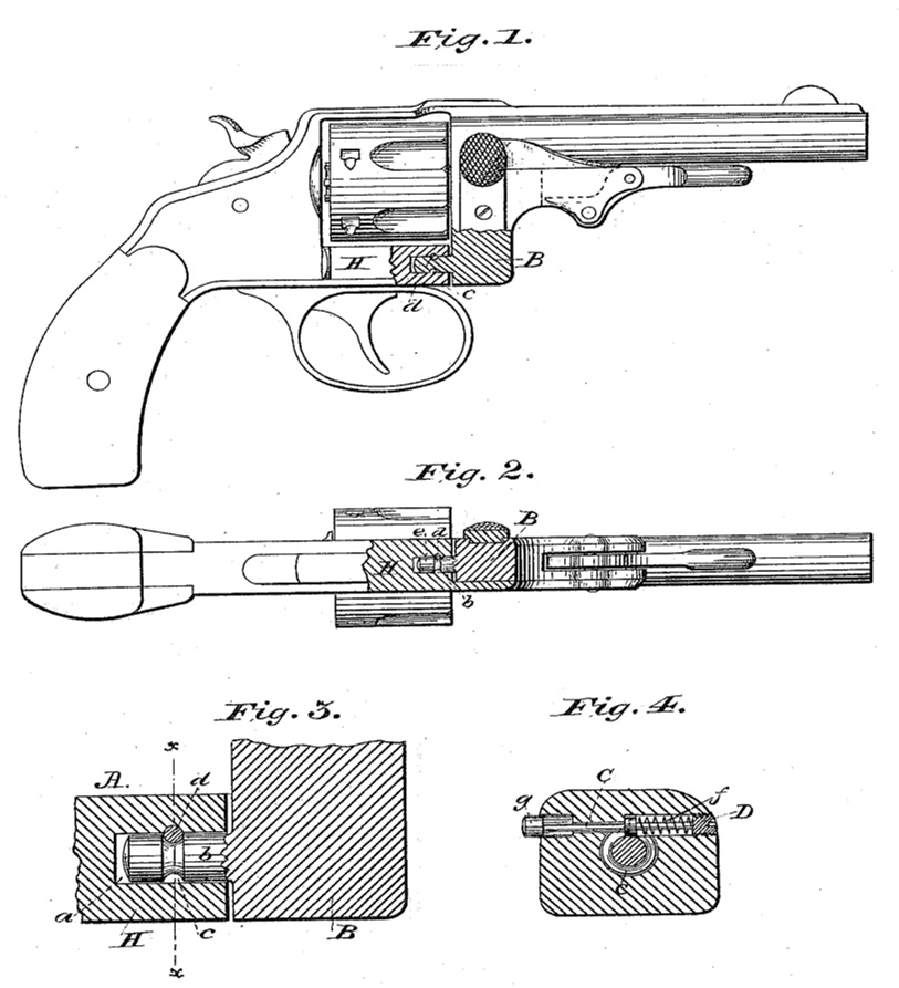
Figure 1 is a side view, partly in section, of a pistol embodying my invention. Fig. 2 is a plan view of the same. Fig. 3 is a longitudinal section of the rotating pin and fastening device. Fig. 4 is a section through line x x of Fig. 3.
A in these drawings designates the main frame or body of the weapon, into which is bored a suitable opening, a, for the reception of the pin, on which the swinging frame B rotates, the form and arrangement of which frame and of the several parts shown in the drawings, but not particularly mentioned herein, are clearly defined in applications filed herewith. The pivot and means of support of the frame B are formed by the projection b. This projection is formed integral with or, if desired, secured in any one of the ways well known in the art to the frame B, and is provided at any suitable point on the portion entering the socket a with a circumferential groove, c, for the reception of the interlocking portion d of the pin C. By the peculiar and novel arrangement of this retaining-pin C, I provide a fastening which holds the rotating frame, through the media of the projection b, firmly in place, and at the same time it may be easily released by a pressure on the exposed milled end g, when it is desired to withdraw the pin from the socket. The locking in place of the projection is accomplished by the enlarged part d of the pin C being placed in the groove of the said projection, into which it fits snugly. To accommodate this pin C, I bore into the frame A an opening–preferably in the left-hand side of the pistol–large enough for the passage of the disk d, which opening extends half the thickness of the said disk beyond the center of the frame, so as to bring the disk approximately over the center of the extension b. Besides this hole, I bore another for the smaller portion, c, of the pin C, and still another for the reception of the button g. A spring, f, is provided, the resiliency of which keeps the pin in the position shown in Fig. 4 by bearing against the screw-stud D, and forcing the disk d against the shoulder h. The cap D has a central opening for the passage of the pin C, and has, as shown, external screw-threads, interlocking with coincident screw-threads on the inner face of the opening. The right-hand end of the pin C is provided with a milled screw-cap, g, which is adapted to be pressed by the finger in releasing the projection b from the disk d. The opening at this end into which the cap is forced should be of a length corresponding with the distance necessarily traveled by the disk d in order to free itself from the pin b.
Having described my invention, what I claim is–
1. In a revolving fire-arm, the swinging portion B of the frame, provided with a cylindrical rearward projection or arm, b, having an annular channel, c, in combination with the main or stationary frame A, provided with a longitudinal recess or seat, a, adapted to receive the arm b, and the spring-actuated catch-bolt C, arranged to interlock with the groove c, whereby the swinging portion is free to rotate upon the extension or arm b, or to be removed longitudinally by releasing the same, substantially as and for the purpose set forth.
2. In a revolving fire-arm, the combination of the locking-pin C, provided with enlarged disk portion d and press-button g, the frame A, bored to receive the same, as described, the spring f, inclosing screw-plug D, and frame B, provided with extension or arm b, having annular groove c, substantially as and for the purpose set forth.
In testimony whereof I have hereunto set my hand in the presence of two subscribing witnesses.
WILLIAM TRABUE.
Witnesses:
JAMES TRABUE,
A.H. ROBINSON.