
US 295064
UNITED STATES PATENT OFFICE.
JOHN T. SMITH, OF ROCKFALL, CONNECTICUT.
REVOLVER.
SPECIFICATION forming part of Letters Patent No. 295,064, dated March 11, 1884.
Application filed December 31, 1883. (No model.)
To all whom it may concern:
Be it known that I, JOHN T. SMITH, of Rockfall, in the county of Middlesex and State of Connecticut, have invented a new Improvement in Revolvers; and I do hereby declare the following, when taken in connection with accompanying drawings and the letters of reference marked thereon, to be a full, clear, and exact description of the same, and which said drawings constitute part of this specification, and represent, in–
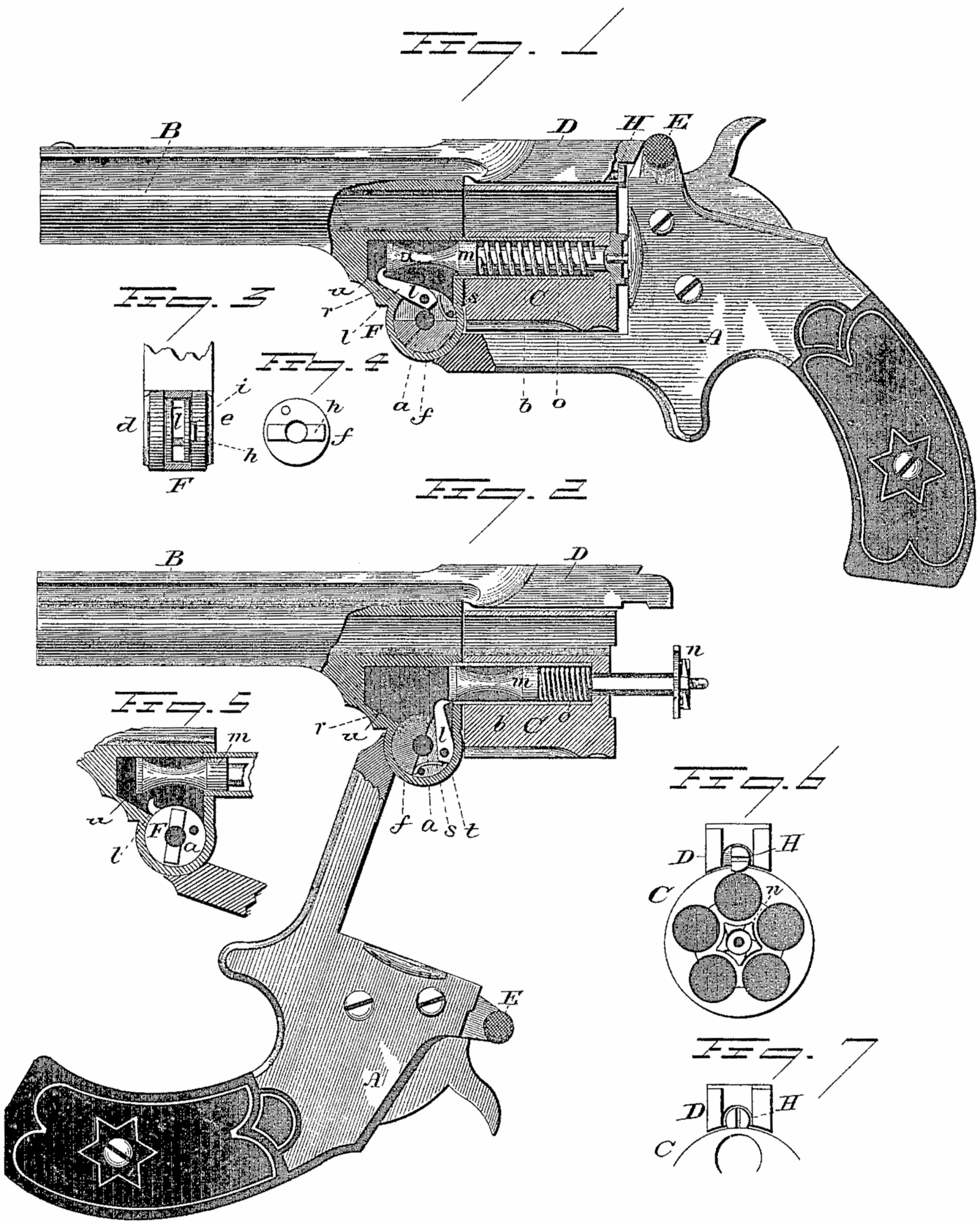
Figure 1, a sectional side view, the parts in the closed position; Fig. 2, the same view, the parts in the open position, and showing the ejector-spindle as just on the point of escaping from the dog; Fig. 3, a face view of the hinge, showing a section through the tongue, and so as to expose the disk; Fig. 4, a side view of the disk; Fig. 5, a sectional side view of the hinge portion, illustrating the operation of the dog in the closing movement; Fig. 6, a rear view of the cylinders, and the arm which extends from the barrel over them, showing the device for locking the cylinder in place; Fig. 7, the same view of the device in the unlocked position.
This invention relates to an improvement in that class of revolvers in which the barrel is hinged in the frame below and forward of the cylinder, and in which the cylinder is hung upon a spindle attached to the barrel or hinged part, and particularly to such revolvers as are provided with an automatic ejector, which operates to eject all exploded shells or cartridges not exploded in the act of turning the barrel upon its hinge, the object being a simple and positive device for forcing the ejector rear ward, and which, when the ejector has been moved rearward, will escape therefrom and permit the ejector to be returned by a spring independent of the device, which moves the ejector rearward; and in such devices as more fully hereinafter described my invention principally consists.
A represents the frame, to which the barrel B is hinged, as at a. At the rear end of the barrel the revolving chamber C is hung upon a hollow pintle, b, and over this cylinder from the barrel an arm, D, extends to engage a locking device, E, in the frame at the rear, all of substantially well-known construction, and therefore do not require detailed description.
The hinge is formed by two cheeks, d e, on the frame, between which a corresponding tongue, F, on the barrel or forward part of the frame stands, as seen in Fig. 3, and through which the pivot a passes in the usual manner. In one side of the tongue F is a concentric chamber, in which lies a disk, f. This disk is connected to one of the cheeks of the frame, preferably by a rib, h, on its side fitting into a corresponding groove, i, in that cheek, as seen in Fig. 3, and so that when in position it stands as if a part of the frame. To this disk f a dog, l, is hung, as seen in Fig. 1, the hinging-point being directly over the pivot a when the barrel is locked to the frame. The nose of the dog in this condition stands in rear of the ejector-spindle m. This spindle is of usual construction, carrying at its rear end the star shaped ejector-plate n, and working freely through a hollow pintle, b, provided within the pintle with a spring, o, the tendency of which is to force the ejector into its place of rest, as seen in Fig. 1, but yet will yield to permit the rear movement of the ejector, as seen in Fig. 2. When the frame and barrel are turned upon their hinge to open the chambers, as seen in Fig. 2, the disk, being substantially a fixed part of the frame, turns with the frame, as seen in Fig. 2, and in so doing the nose of the dog l, bearing against the end of the spindle m, forces that spindle rearward, as seen in Fig. 2, until in the movement of the disk the nose of the dog is drawn downward and away from the end of the spindle, as seen in Fig. 2. Then the spindle will escape from the nose of the dog and be thrown backward by the action of its own spring, and while the chambers are open and exposed. Then, when the barrels are closed, and in the closing movement, the back of the dog strikes an incline below the spindle, as seen in Fig. 5, which arrests the further rotary movement of the dog; but the continued rotary movement of the disk causes the dog to travel up the incline until its nose arrives to a position in rear of the spindle, as seen in Fig. 1. To hold the dog in the position where it stands when the spindle escapes it, as seen in Fig. 5, a spring, s, is arranged on the disk to bear upon the flat side t on the rear end of the dog. By this spring the dog will be held in the position seen in Fig. 2 until it arrives upon the incline r, as seen in Fig. 5. Then the spring s yields to permit the dog to turn to the position seen in Fig. 1, and in which turning the spring passes from the flat side t to a point above it, where it acts to hold the dog up against the rear end of the spindle. To permit the dog to return, the spindle is recessed forward of its rear end, as at u. To insure the nose of the dog holding its engagement with the end of the spindle, I make it slightly hook shape and the rear end of the spindle concave, as seen in Fig. 1. To secure the cylinder in place, and so as to prevent its accidental removal, I introduce a screw, H, into the rear end of the arm D, and so that the head of the screw will overlap the rear end of the cylinder, as seen in Figs. 1 and6. One side of this head is cut away, as seen in Fig. 7, and so that when the screw is turned to the position seen in Fig. 7 the screw-head does not reach onto the cylinder, and in that position the cylinders may be removed; but when turned to the position seen in Fig. 6, then the head overlaps the end of the cylinder to secure it in place. The head of this screw is nicked, so that with any suitable instrument it may be readily turned from one position to the other. This makes a simple and cheap locking device for the cylinder, and one which does not interfere with the mechanism of the arm.
I claim–
1. In a revolver, the combination of the frame and barrel hinged together forward of and carrying the cylinder, the ejector-spindle moving longitudinally through the cylinder, its forward end extending into a recess above the hinge, the disk f within the hinge and fixed to the frame, so as to turn with it, the dog l, hinged to said disk, its nose constructed and arranged to engage the forward end of the spindle when in the closed position, and so that in the opening movement the said dog will force the ejector-spindle rearward and escape therefrom at the extreme rear position of cape therefrom at the extreme rear position of the ejector-spindle, and a spring arranged to force said spindle rearward so soon as it escapes from the dog, substantially as described.
2. The combination of the frame A, barrel B, hinged thereto forward of and carrying the cylinder, the disk f, arranged in a recess in the hinge, but fixed to the frame, the dog l, hinged to said disk, the ejector-spindle moving longitudinally through the cylinder, its forward end extending into a recess above the dog, the barrel or forward hinged portion constructed with the incline r forward of the hinge, and upon which the dog l will strike in the closing movement, substantially as described.
3. The combination of the frame A, barrel B, hinged thereto forward of and carrying the cylinder, the disk f, arranged in a recess in the hinge, but fixed to the frame, the dog l, hinged to said disk, the ejector-spindle moving longitudinally through the cylinder, its forward end extending into a recess above the dog, the barrel or forward hinged portion constructed with the incline r forward of the hinge, and upon which the dog l will strike in the closing movement, the said dog constructed. With a flat surface, t, and a spring, s, arranged to bear upon said flat surface, whereby the said dog is held in the open position, substantially as described.
4. The combination of the frame A, barrel B, hinged thereto forward of and carrying the cylinder, the disk f, arranged in a recess in the hinge, but fixed to the frame, the dog l, hinged to said disk, the ejector-spindle moving longitudinally through the cylinder, its forward end extending into a recess above the dog, the barrel or forward hinged portion constructed with the incline r forward of the hinge, and upon which the dog l will strike in the closing movement, the ejector-spindle constructed with a recess u, substantially as described.
5. In a revolver, the combination of the frame and cylinder with the headed screw H, introduced in the end of the arm above the cylinder, and so as to overlap the rear end of said cylinder, one side of the said head removed, substantially as and for the purpose described.
JOHN T. SMITH
Witnesses:
JOHN T. DUNNEL,
V. H. COLES.