
US 263551
UNITED STATES PATENT OFFICE.
WILLIAM MASON, OF HARTFORD, CONNECTICUT, ASSIGNOR TO THE COLTS PATENT FIRE-ARMS MANUFACTURING COMPANY, OF SAME PLACE.
REVOLVING FIRE-ARM.
SPECIFICATION forming part of Letters Patent No. 263,551, dated August 29, 1882.
Application filed March 25, 1882. (No model.)
To all whom it may concern:
Be it known that I, WM. MASON, of Hartford, in the county of Hartford and State of Connecticut, have invented a new Improvement in Revolving Fire-Arms; and I do hereby declare the following, when taken in connection with accompanying two sheets of drawings and the letters of reference marked thereon, to be a full, clear, and exact description of the same, and which said drawings constitute part of this specification, and represent, in–
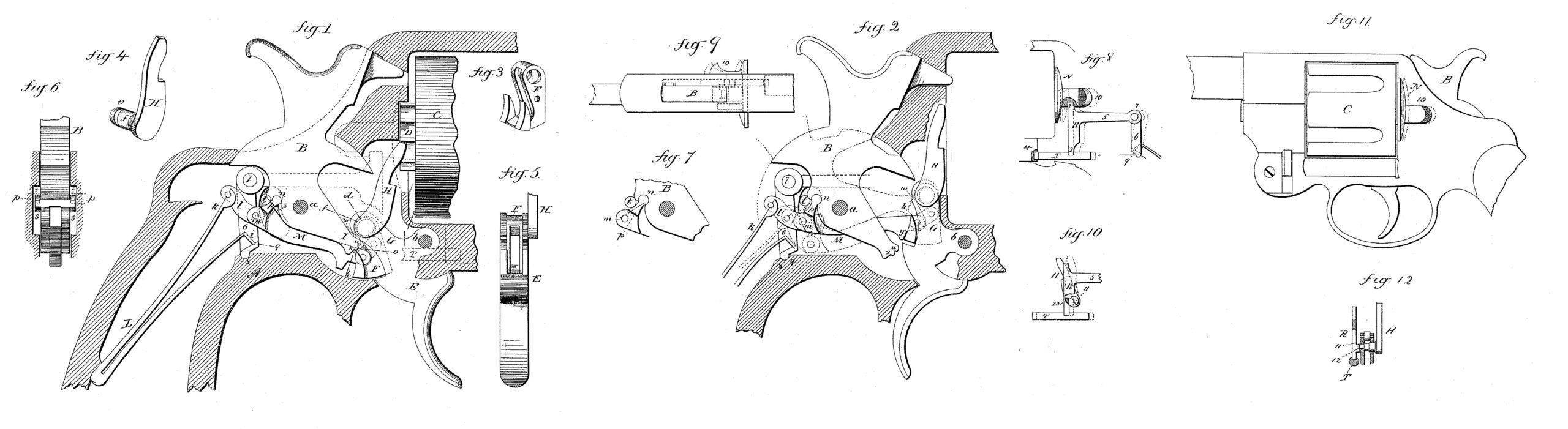
Figure 1, a sectional side view, showing the parts in their normal condition; Fig. 2, the same immediately after the discharge of the hammer; Figs, 3 to 10, inclusive, detached parts; Fig. 11, side view, showing a swinging frame, to which the cylinder is hung, and the movable part of the shield; Fig. 12, detailed view, showing the pawl and the cylinder-locking mechanism in front view detached.
This invention relates to an improvement in revolving fire-arms and locks therefor, parts of which are applicable to other classes of arms, the object of the invention being to dispense with the independent springs employed in operating the trigger, pawl, and the cylinder-locking device, and employ the main spring for all these devices.
Another object of the invention is to avoid go the fiction of the usual rebounding movement required in throwing the hammer backward after it has delivered its blow, so as to take its lose back out of the way for the movement of the chamber to present the next cartridge; and the invention consists in the details of construction, as hereinafter described, and more particularly recited in the claims.
A represents the frame or receiver, which is of the usual form, within which the mechanism is arranged; B, the hammer, hung upon its pivot a; C, the cylinder; D, the ratchet on the end of the cylinder, its rear end working in a recess in the frame in the usual manner, and as seen in Fig. 1; E, the trigger, hung upon a pivot at b; F, the sear, shown detached in Fig. 3. The sear (Fig. 3, perspective,) is hung upon a pivot, d, in the arm G of the trigger. This pivot is a trunnion, e, on the pawl H, (seen detached in Fig. 4, perspective,) the trunnion extending through the arm G of the trigger, and the sear hung upon the trunnion within a recess in the rear side of the arm G, as seen in Fig. 5. That part of the trunnion which lies in the arm each side the recess is cylindrical, but that portion within the recess is cut away upon the rear side, as at f, as seen in Fig. 4, and in broken lines, Fig. 1, which brings the sear to a bearing on that cut-away portion forward of a vertical line through the trunnion, so that any downward pressure exerted upon the sear tends to turn the upper end of the pawl forward toward the cylinder.
The nose h of the sear hangs in a position to engage the notches in the tumbler-arm I of the arm, as seen in Fig. 1, so that by pulling the trigger the arm G will be raised, as seen in Fig. 2, carrying with it the hammer, because of the engagement of the sear with the tumbler, as seen in Fig. 1, and in broken lines, Fig. 2. As this movement will be made against the mainspring of the arm, it follows that the resistance to the pulling of the trigger and raising of the sear will be the power of the mainspring, and this power will therefore be applied through the sear to the pawl H, serving to hold the pawl in connection with its ratchet while the hammer is being cocked.
The mainspring L is of usual form, one arm resting upon a seat, i, prepared for it in the receiver, or upon a part for independent operation, as shown and hereinafter described, the other arm, k, engaging a link, l, which is hung to the rear end of a lever, M, as at m. The lever M takes its bearing on the hammer, as at n, in rear of the pivot, this bearing a forming the fulcrum of the lever M, the connecting pivot in between the lever M and the link l being below the bearing in on the hammer. The other end of the lever M is hung by a link, o, to the sear F, as seen in Fig. 1. The main spring therefore tends to force the lever M toward the hammer, and thus apply the power of the spring to the hammer in rear of its pivot. At the same time the mainspring acts upon the sear through the lever M, tending to draw it toward the tumbler of the hammer, and, exerting a downward force upon the sear, also applies the power of the mainspring to the strikes the sear and forces it forward out of pawl H, as before described. Therefore by pulling the trigger in the usual manner for self-cocking the hammer is thrown back, the parts brought into the position seen in broken lines, Fig. 2, and the mainspring compressed. Thus the mainspring serves as a spring for all the parts of the lock.
To retract the hammer after it has imparted its blow, and yet not retard the action of the mainspring, that part of the lever M which extends up to take its bearing at n in the hammer is constructed with projections p upon one or both sides, which extend into a recess, s, in the receiver, as seen in Fig. 6, and work in that recess in the movement of the hammer in cocking and returning. The hammer leaves the sear, or, rather, the sear escapes from the hammer, as seen in Fig. 2, when at full-cock, and before the trigger can be released from the power of the finger, which pulled it, which leaves the lever M in its position seen in Fig. 2, and from which it will return to the position seen in Fig.1 so soon as the power of the finger is taken from the trigger. In the recesses s, through which the projections p work, is a stud, t, against which the projections p will strike as they approach their extreme rear or normal position, and these stops are arranged so that the projections will strike them upon a point between the bearing in on the hammer and the pivot m of the link l, which is the position seen in Fig. 7. Then as the spring continues its action it draws upon the lever M at the point m rearward. The projections p operating upon the studs t as a fulcrum causes the bearing-point n of the lever to throw forward, as indicated in broken lines, Fig. 7; and this forward movement of the bearing-point n in rear of the hammer-pivot causes the hammer to turn backward, as seen in Fig. 1, and take its nose away from the primer which it struck, and out of reach of the next advancing cartridge. This final turning of the lever M upon the fulcrum t brings the trigger as well as the pawl H back for re-engagement. By this construction and arrangement the full power of the spring is continued upon the hammer throughout its stroke, and held upon the hammer until the trigger is released. Then in the reaction of the mainspring the hammer is turned back as by a lever upon a fulcrum, and without the rebounding like movement in other constructions.
The hammer may be cocked by hand, and in so doing the tumbler-arm strikes upon the under side of the arm G of the trigger, there by forcing the trigger upward until the notch u on the tumbler engages a corresponding shoulder, w, on the trigger-arm, from which it will be released in the usual manner.
When cocking by the trigger the nose h of the sear engages the notch x, as seen in Fig. 1, and turns the hammer backward, as before described, and when it arrives at the position of full-cock a shoulder, y, on the lever M engagement with the tumbler, and so as to release the hammer to permit it to be forced forward, as before described.
The projections p on the lever M, and the recesses s in the receiver, are made to enable the body of the hammer to pass the fulcrum stud t, but they may be otherwise arranged, it only being essential that there shall be a stop in the path of the returning lever by which the mainspring is engaged with the hammer, to serve as a fulcrum over which that lever will oscillate to turn its bearing-point upon the hammer forward and downward.
In order to open the recess in the frame in which the ratchet of the cylinder stands, the part N of the shield on one side is made to move backward, as indicated in broken lines, Figs. 8, 9, and 11, in the usual and well known manner, so that when drawn back the cylinder may be turned outward, away from its position in the frame, or returned, and when so returned the part of the shield is again moved forward to close that recess–a device well known in revolvers.
To make the return of the shield automatic, through the action of the mainspring, I arrange a sliding T-shaped piece, R, one end, 2, of the cross of the T engaged with an inward extension from the shield, as seen in Fig.9, the other end, 3, engaged with the bolt T, as seen in Fig. 8, this bolt being the locking-bolt which holds the swinging part of the frame that carries the cylinder, and is arranged longitudinally in the receiver, so as to throw forward into that swinging part 4 when in place, as seen in Fig. 8, thus locking that swinging part in place. This bolt is also a well-known arrangement.
The leg 5 of the slide R extends rearward, and is hinged to a lever, 6, as at 7, the lever 6 resting in a socket, 8, in the frame, as seen in Figs. 1 and 2. At its lower end the lever 6 is constructed with a bearing, 9, for the arm i of the mainspring, forward of its bearing-point 8, so that the force of the mainspring is applied to the lever 6 forward of its pivot, tending thereby to force the upper end of the lever and the parts connected to it forward.
When the operator desires to remove the cylinder he draws back the part N of the shield by means of the finger-piece 10, as indicated in broken lines, Fig. 8, which, through the slide R, draws the bolt T backward and away from its engagement with the cylinder frame, turning the lever 6 to the rear, as seen in broken lines, Fig. 8. This movement raises the mainspring bearing-point 9, and to that extent compresses the mainspring, so that when the parts are free the mainspring will act to force them forward. Thus the power of the mainspring is utilized to lock the cylinder, and the usual spring or springs for the bolt and for the shield are avoided.
It frequently occurs in attempts to remove or replace the cylinder that the pawl interferes with so doing. To overcome this difficulty and take the pawl back out of the way, I make the trunnions of the pawl to project beyond the opposite side of the trigger and cut its front face flat, as seen at 11, Fig. 10, the flat face inclining toward the cylinder; and on the slide R, I form a shoulder or projection, 12, which stands in front of the flat face 11 of the trunnion, as seen in Fig. 12, and free from it when the cylinder is locked; but when the slide R is drawn backward, as for unlocking the cylinder, the flat face 11 of the extension of the trunnions stands in the path of the projections 12, and is struck by it, and because of the inclination of the face 11 it will strike above the center of motion and turn the pawl backward, as seen in broken lines, Fig. 10, and will there hold it until the slide is permitted again to return, as in locking the cylinder, so that before the cylinder can be removed the pawl has been thrown back out of its way, and will in like manner be thrown back out of its way before the cylinder can be returned.
The flat face 11 of the trunnion is made because of its simplicity; but it will be readily seen that any projection or shoulder on the trunnion above its center of motion will accomplish the object.
I claim–
1. The combination of the hammer and the trigger with a lever in connection with the trigger, and bearing on the hammer in rear of its pivot, and engaged with the mainspring, whereby the power of the mainspring is applied to the hammer in rear of its pivot, and a fulcrum, t, arranged in rear of the lever and below its bearing-point on the hammer, over which fulcrum the said lever will operate after the hammer has been thrown forward to impart to the hammer a retreating movement, substantially as described.
2. The combination of the hammer B, the trigger E, the sear F, hung therein, and the lever M, hung by one end to said sear, its other end connected by a link to the main spring, and having its fulcrum in the hammer in rear of its pivot and at a point above the link-connection between the mainspring and lever, with the stud t arranged in the path of the lever between its bearing-point on the hammer and its link-connection, substantially as and for the purpose described.
3. The combination of the hammer B, the trigger E, the pawl H, having its trunnion in the trigger, constructed with an eccentric bearing, f, the sear F, hung upon said eccentric bearing f in the trigger, and the lever M, hung by one end to said sear, its other end connected by a link to the mainspring, and having its fulcrum in the hammer in rear of its pivot and at a point above the link-connection between the mainspring and lever, with the stud t arranged in the path of the lever between its bearing-point on the hammer and its link-connection, substantially as and for the purpose described.
4. In a revolver, the combination of the movable part N of the shield, the locking-bolt T, and the slide R, engaged with both the shield and bolt, and hung to a lever, 6, taking its bearing in the receiver, with the mainspring, one arm of which bears upon said lever 6 forward of its fulcrum, substantially as described.
5. The combination of the slide R, in connection with the movable part N of the shield, and constructed with a shoulder, 12, with the pawl H, constructed with a projection, 11, which stands in the path of said slide, substantially as and for the purpose described.
WILLIAM MASON.
Witnesses:
JOHN E. EARLE,
JOS. C. EARLE.