
US 251306
UNITED STATES PATENT OFFICE.
OTIS A. SMITH AND JOHN T. SMITH, OF MIDDLEFIELD, CONNECTICUT; SAID JOHN T. SMITH ASSIGNOR TO SAID OTIS A. SMITH.
REVOLVING FIRE-ARM.
SPECIFICATION forming part of Letters Patent No. 251,306, dated December 20, 1881.
Application filed October 28, 1881. (No model.)
To all whom it may concern:
Be it known that we OTIS A. SMITH and JOHN T. SMITH, of Middlefield, in the county of Middlesex and State of Connecticut, have invented a new Improvement in Revolvers; and we do hereby declare the following, when taken in connection with the accompanying drawings and the letters of reference marked thereon, to be a full, clear, and exact description of the same, and which said drawings constitute part of this specification, and represent, in–
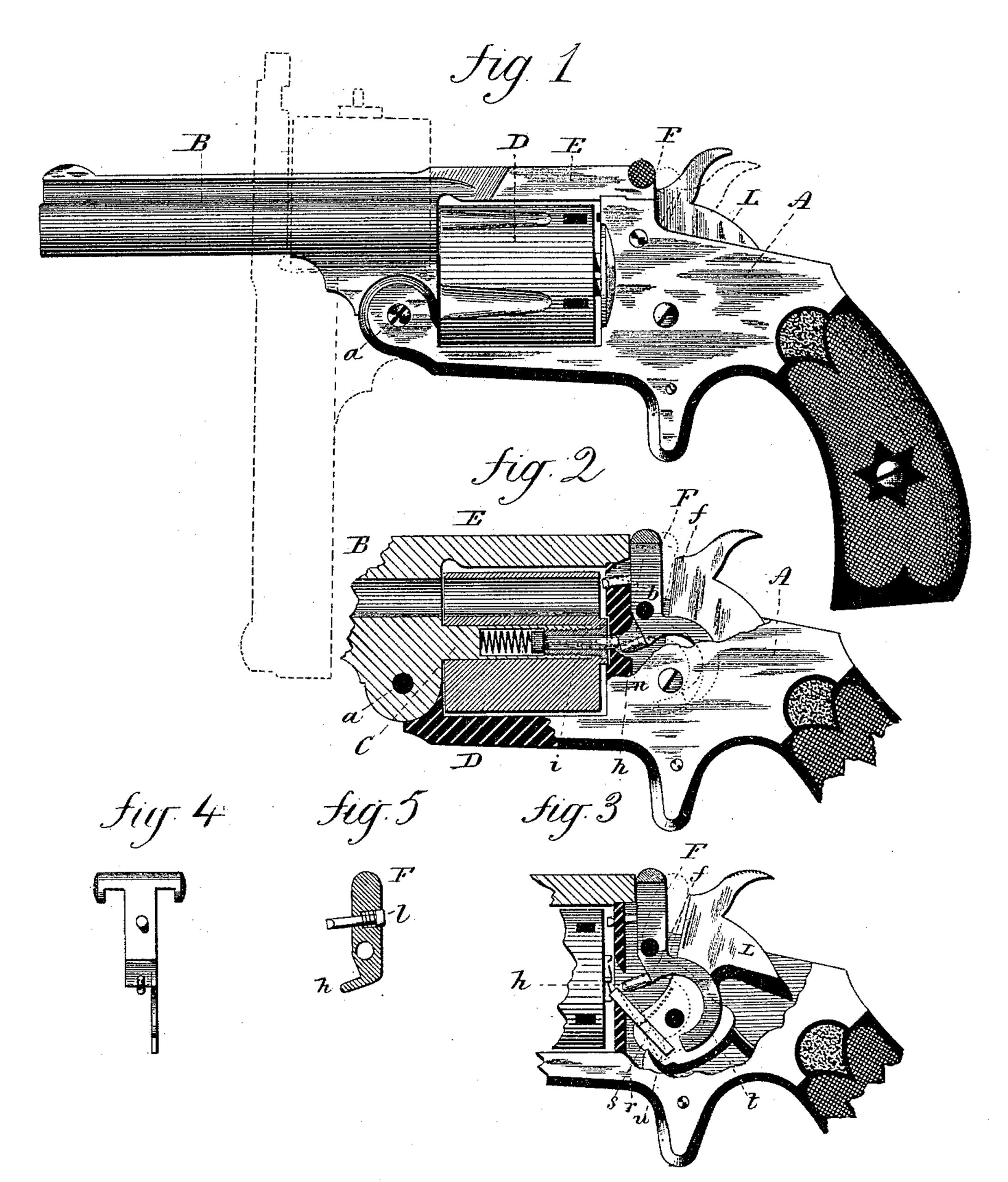
Figure 1, a side view, Fig. 2, a longitudinal section, Fig. 3, a side view, of the mechanism of the arm; Figs. 4 and 5, detached views.
This invention relates to an improvement in that class of revolvers in which the barrel and cylinder are hinged to the forward end of the frame, so as to turn down in a vertical plane, commonly called “break-downs” or “tilting up at the breech,” parts of which are applicable to other arms of the break-down or tilting up class, the object of the invention being principally to make a convenient means for securing the barrel when in place; and it consists in a latch, pivoted in the receiver in rear of the barrel, extending upward, to engage the barrel when closed, and downward from the pivot, combined with a spring device in the rear end of the tilting part, which, as the tilting part returns to place, will strike the said latch below its pivot and throw the upper end forward into engagement with the tilting part, and so as to hold said tilting part in place, as more fully hereinafter described.
We represent the invention as applied to a revolver only, and we represent the revolver as one of common outline or appearance, in which A is the frame, to which the barrel B is hinged at the forward end, as at a provided with a center-pin, C, on which the cylinder D is arranged, with an arm, E, extending rearward from the barrel to engage the frame in the usual manner, as seen in Fig. 1, and so that when disengaged the barrel may be tilted, taking with it the cylinder, as seen in broken lines, Fig. 1, also in the usual manner.
In the frame in rear of the cylinder a lever like latch is hung upon a pivot, b, its upper arm F, extending vertically upward, terminating in a T shape at the top, as seen in Fig. 4, so as to engage the part E of the barrel, as seen in Fig. 3, or turned to the rear upon its pivot to disengage the barrel, as indicated in broken lines, Fig. 3. The T part extends to each side, so as to form convenient means for the thumb and finger to operate the latch; or other devices may be arranged for moving the lever. The other arm, f, extends forward, as at h, to near the front face of the rear end of the cylinder-recess.
In the center-pin is a spring-bolt, i, which projects at the rear end of the center-pin, and so as to strike the arm f, or a projection, h, thereon, as seen in Fig. 2, through an opening in the frame. When the latch is turned back to release the barrel, as indicated in broken lines, Fig. 2, the lower arm, f, or the projection l, therefrom, forces the spring-bolt i into the center-pin and out of the opening in the frame, so that the barrel may be tilted in the usual manner. Then when the barrel is returned the spring-bolt strikes the face of the frame and passes down against the face, being thereby forced inward until it comes to the opening n in the frame, which is when the barrel is completely returned. Then the bolt springs rearward, acting upon the latch below its pivot, so as to throw the upper end, F, forward into engagement with the barrel, as shown, and so as to hold the barrel firmly in place.
It will be readily seen that this device for securing the barrel may be applied to other break-down or tilting arms-that is to say, by simply arranging the spring-bolt at some point in the rear end of the barrel or barrels, so that it will strike the locking-latch below its pivot to throw the latch forward to engage the barrels when closed. This part of the invention, therefore, is not to be understood as limited to revolvers.
In the latch we arrange a firing-pin, l, which the hammer L will strike as it is thrown forward, the pin being loose in the latch or free for longitudinal movement. Then when the latch is drawn backward to release the barrel, as seen in broken lines, Fig. 2, the firing-pin will also be drawn backward out of the way of the barrel or the cylinder, to allow the barrel to be tilted. This movement of the firing-pin may also be made in other tilting fire-arms.
r is the hand or pawl, pivoted to the hammer L, as at s, with a spring applied to force the nose of the pawl forward into engagement with the ratchet on the rear end of the cylinder, and so that when the hammer is turned the pawl will engage the ratchet on the cylinder and rotate the cylinder in the usual manner. To take the pawl out of the way of the cylinder when it is desired to tilt the barrel, an arm, t, extends from the arm f of the latch downward, and so that when the latch is turned backward to release the barrel the said arm t will strike the lower arm u of the pawl and turn its nose away from the ratchet, as seen in Fig. 3; hence the nose of the pawl cannot project beyond the face-of the receiver until the barrels are fully closed, because it will be held back by the arm t until the barrel is closed. As the hammer lies against the firing-pin and latch, and thus holds the latch closed, the disengagement of the barrel cannot be made while the hammer is down; but on drawing the latch backward to disengage the barrel the hammer must necessarily be moved with the latch, and the movement of the latch is therefore made sufficient to bring the hammer to half-cock, as seen in Fig. 3, before the disengagement of the barrel. The latch also prevents the hammer from striking an effective blow until it is completely engaged.
We claim–
1. In a fire-arm in which the barrel is pivoted forward so as to tilt up at the breech, the combination of a lever hung in the frame, one arm of which extends upward to engage the barrel when closed, the other extending downward from the pivot, with a spring-bolt in the tilting part arranged to strike the arm of the lever below its pivot as the barrel approaches its closed position, and so that the force of the said bolt will turn the upper arm forward to lock the barrel in its closed position, substantially as described.
2. In a fire-arm in which the barrel is pivoted forward so as to tilt up at the breech, the combination of a lever hung in the frame, one arm of which extends upward to engage the barrel when closed, the other extending downward from the pivot, with a spring-bolt in the tilting part arranged to strike the arm of the lever below its pivot as the barrel approaches its closed position, and so that the force of the said bolt will turn the upper arm forward to lock the barrel in its closed position, with a firing-pin arranged in the upper arm of said lever free for longitudinal movement, substantially as described.
3. In a revolver, the combination of a lever hung in the frame and in rear of the cylinder-recess, one arm of which extends upward from the pivot to engage the barrel when closed, a pawl or land pivoted to the hammer to engage the ratchet on the cylinder when the hammer is turned, and an arm extending from said lever below its pivot to engage with the said pawl below its pivot, whereby the turning of said lever backward to release the barrels also turns the said hand away from its position of engagement with the ratchet, substantially as described.
OTIS. A. SMITH,
JOHN T. SMITH.
Witnesses:
VALERIUS E. COLES,
HENRY C. WILCOX,