
US 311383
UNITED STATES PATENT OFFICE.
JOHN T. SMITH, OF ROCK FALL, CONNECTICUT.
LOCK FOR REVOLVERS.
SPECIFICATION forming part of Letters Patent No. 314,067, dated March 7, 1885.
Application filed November 10, 1884. (No model.)
To all whom it may concern:
Be it known that I, JOHN T. SMITH, of Rock Fall, in the county of Middlesex and State of Connecticut, have invented a new Improvement in Revolvers; and I do hereby declare the following, when taken in connection with accompanying drawings and the letters of reference marked thereon, to be a full, clear; and exact description of the same, and which said drawings constitute part of this specification, and represent, in–
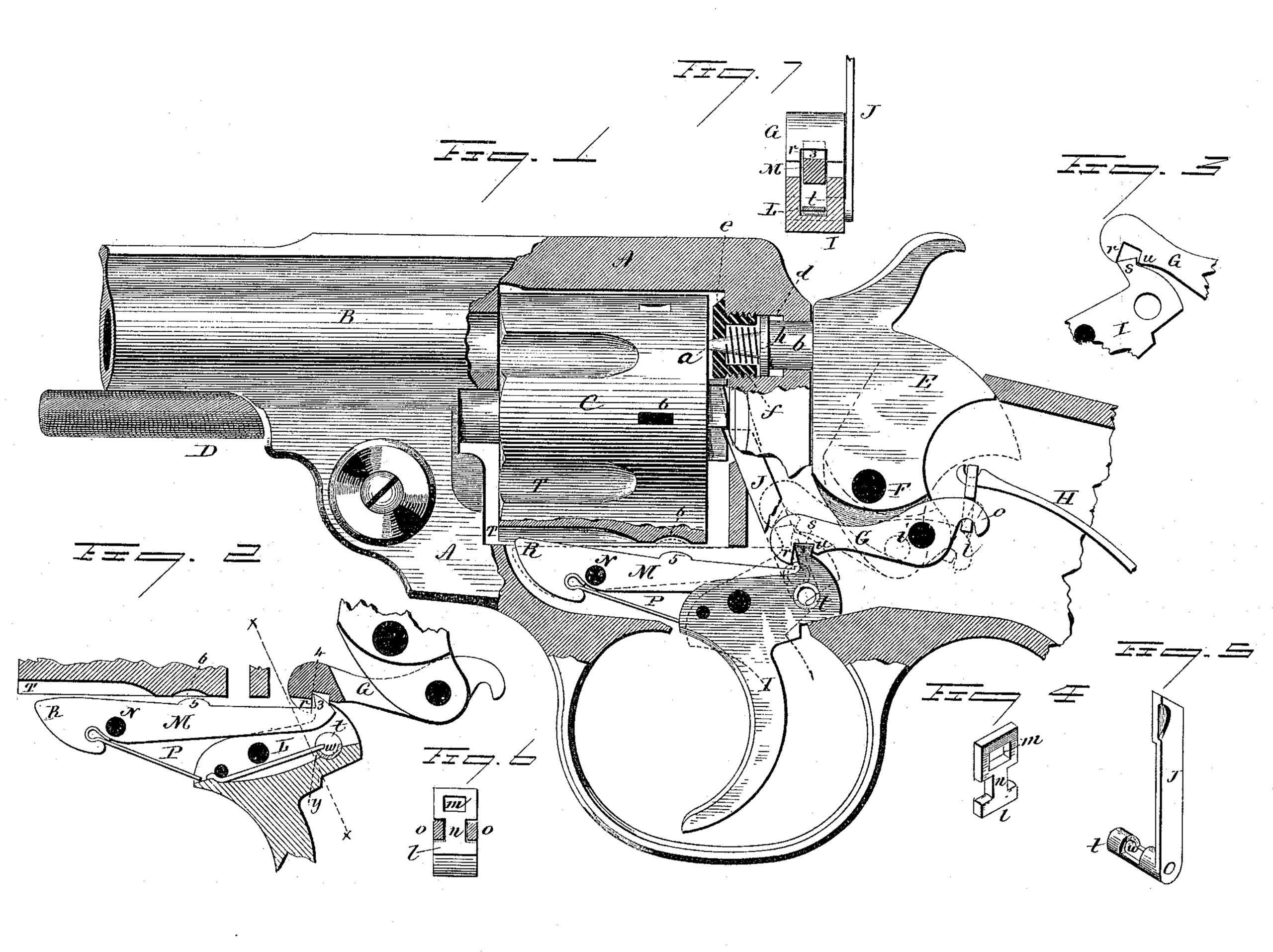
Figure 1, a sectional side view; Fig. 2, a detached view of the trigger and its immediately-connected mechanism; Fig. 3, a detached view showing the action of the shoulder u upon the trigger; Fig. 4, a perspective view of the stirrup detached; Fig. 5, a perspective view of the cylinder-dog detached; Fig. 6, a rear view of the ever G, showing the stirrup in place; Fig. 7, a section on line x x of Fig. 2, looking rearward.
This invention relates to an improvement in that class of revolvers which are made self cocking–that is to say, in which the hammer may be thrown to full-cock and discharged by a continuous pull of the trigger, parts of the invention being applicable to other classes of revolvers and locks of other fire-arms; and the invention consists in the construction and combination of parts, as hereinafter described, and particularly recited in the claims.
The frame A of the revolver, as here represented, is solid, provided at its forward end with a barrel, B, which is also made as a part of the frame; C, the cylinder, which is made removable from the frame for loading and unloading by means of a movable spindle, D, this spindle being arranged to be drawn forward from the cylinder, so that the cylinder may be taken out at one side or returned into its recess in the usual manner for solid-frame revolvers; E, the hammer, is hung upon a pivot, F, at the rear, also in the usual manner.
The firing-pin is arranged in the frame, so that its forward end, a, may protrude into the cylinder-recess and strike the head of the cartridge, its rear end, b, extending through the frame to receive the blow of the hammer. In order to insure the retracting of the firing pin upon the cocking of the hammer before the rotation of the cylinder, a spring or mechanical action is necessary upon the firing pin. To accomplish this in a solid-frame revolver, I bore into the rear or recoil portion of the frame and in axial line with the barrel a recess, d, extending nearly through that part of the frame, and then continue the opening through the frame in a reduced diameter. The forward end of the recess is tapped, and into this forward tapped end of the recess a bolster, e, is introduced. This bolster is recessed upon its rear side to form a spring chamber, f, the head of the bolster having a central opening corresponding to the forward or striking end of the firing-pin.
The firing-pin is constructed with an annular flange or collar, or other suitable stop, h, of larger diameter than the recess f in the bolster. The rear portion of the firing-pin is cylindrical in shape, and so as to work freely through the opening in the rear portion of the frame, and serve as a guide for the movement of the pin. In the spring-chamber f and forward of the collar h a spring is introduced, its forward end seated in the bolster, its rear end against the collar on the firing pin, and so that the action of the spring is to force the firing-pin rearward when the hammer is turned therefrom, and so as to draw the point or nose a of the firing-pin back out of the way of the revolving cylinder. By this construction I am enabled to drill the frame for the firing-pin through the barrel, and introduce the firing-pin from the front rearward–a simple, cheap, and effective construction.
To the hammer, on a pivot, i, below the hammer-pivot, F, I hang a lever, G, to the rear arm of which the mainspring H is engaged. In order that there may be freedom of action between the mainspring and the lever H, a link-connection of some character is necessary between the two, and to make this connection simple and cheap I have devised the stirrup seen in perspective, Fig. 4. This is cut from sheet metal. The lower end is of T shape. The cross l of the T is engaged with the lever. The other end of the stirrup has an opening, m, through which the end of the mainspring passes, as seen in Fig. 1. The end of the lever G is hook-shaped and bifurcated, so that the tail n of the T passes between the two parts of the lever, the cross engaging the two sides, as seen in Fig. 6, o representing the two prongs of the lever. This construction of stirrup is inexpensive and securely couples the spring with the lever, and permits the greatest freedom in action of both parts.
The forward end of the lever G is constructed in the form of a hook, r, with which the nose s of the trigger I engages, and so that upon a pull of the trigger the lever G will be drawn forward, as indicated in broken lines, taking with it the hammer. So far this is a known construction for cocking the hammer by the trigger.
To the trigger the usual pawl, J, is hung, as at t, and so that as the trigger is pulled in the act of cocking the cylinder will be rotated, the hammer escaping after the cylinder has been turned to present a new chamber in axial line of the barrel.
In order that the cylinder may be rotated by means of the hammer–that is, by applying the thumb to the hammer as in the act of cocking–it is necessary to make some connection between the hammer and the dog J. To do this I construct the lever G with a shoulder, u, in rear of the hook r, and so as to form a recess between the said hook r and shoulder u, and into which the nose s of the trigger will enter. As the trigger is pulled, its back acts as a can upon the under side of the lever G to raise the forward end of the lever until the hooked end r shall escape from the nose of the trigger, as seen in Fig. 3. When the hammer stands in its down position, as seen in Fig. 1, the shoulder u is in rear of the nose of the trigger, and so that if in that condition the hammer be moved rearward by means of its thumb-piece the shoulder u will bear against the rear side of the noses of the trigger and turn that end of the trigger upward and forward, as indicated in broken lines, Fig.1, which, movement imparts to the dog J a corresponding movement to give the cylinder its required rotation. The throw of the trigger in cocking the hammer and moving the dog J is so great that a considerable extent of rotation is necessarily imparted to the pivot end t of the dog J. If the spring be applied upon a flat surface of this pivot t, as in the usual construction, the spring necessarily rubs upon the surface, creating great friction, and consequently detracts from the free action of the dog. To overcome this difficulty, and cause the spring to act as upon one arm of a lever, I recess the bearing-face of the pivot t, as at w, Fig. 2, and as also seen in Fig. 5. This is best done by boring through the pivot to make it of tubular shape. The forward edge of this recessed portion forms a bearing, y, upon which the active end of the spring L bears, as seen in Fig. 2. This bearing y, as it turns downward in the act of pulling the trigger, permits the end of the spring L to pass into the recess w, and so that the spring acts from first to last on this bearing y, as if upon the end of a short arm on the hub of the dog J, giving a greater freedom of action and upon a flat surface on the pivot or hub of the dog.
In the frame forward of the trigger a lever, M, is arranged upon a pivot, N. From its under side a spring, P, extends into a recess in the trigger, forward of the pivot of the trigger, as seen in Fig. 2, and so that this spring acts as a spring for the trigger. The lever M. extends to the rear through a groove in the upper surface of the trigger, and at its extreme rear end it is constructed with a shoulder, 3, which at half-cock will engage a corresponding shoulder, 4, on the lever G, as seen in Fig. 1, and that the hammer may be turned backward from the firing-pin and caught by the shoulder 3 at half-cock, as seen in Fig. 2, which will permit the firing-pin to retreat from contact with the cartridge that may then be in the chamber in the cylinder. The lever M is turned from the position seen in Fig. 1 to that in Fig. 2 in thus engaging the lever G by the action of the spring P.
When the hammer is in the down position, the forward arm, R., of the lever extends up into the cylinder-opening, and into a recess, T, in the cylinder, so that when the hammer is in the down position–that is, all the parts in their normal condition–the arm R acts as a stop to prevent the rotation of the cylinder; but when the hammer is moved to half-cock, then the arm R is turned down into its recess in the frame and out of the path of the rotating cylinder at the position of half-cock. Therefore in that position of the parts the cylinder is free for rotation or for removal from or introduction to its opening in the frame. As the hammer passes on to full-cock, the lever M continues to turn upon its pivot until a projection, 5, on its upper surface enters a corresponding recess, 6, in the cylinder, as seen in broken lines, Fig. 1, and so as to lock the cylinder when so engaged. This engagement occurs in the last part of the cocking movement and just as the dog J ceases its rotative action upon the cylinder, and so that the locking of the cylinder occurs just as the hammer is being discharged. This method of locking the cylinder at the time of discharge is illustrated and described in another application of my own.
Instantly on the release of the trigger the forward arm, R, of the lever is thrown up into engagement with the cylinder, so as to prevent rotation of the cylinder, and retain it still in the locked position until the hammer shall be turned to half-cock, as before described.
I claim–
1. In a revolver, the rear or recoil of the frame, constructed with the recess d, in substantially axial line with the barrel, an opening from the recess through the frame, but of less diameter than the recess, combined with the bolster e, arranged in the forward end of said recess, the said bolster constructed with a central opening through it and recessed up much less friction than when the spring works on its rear side to form a spring-chamber, the firing-pin arranged in the recess in the frame, its forward end extending through the opening in the bolster, its rear end through the opening in the frame, and constructed with a collar within the recess in the frame, and a spring arranged in the recess in the bolster, to take its bearing rearward upon the firing pin, substantially as and for the purpose described.
2. The combination of the hammer E, provided with a bifurcated hook in rear of its pivot, the mainspring, and a stirrup constructed at its lower end of inverted-T shape, its upper end constructed with an opening, M, the said stirrup arranged the tail of the T between the prongs of the hook, the cross of the T in the hook, and the forward end of the mainspring in the recess in the upper end of the stirrup, substantially as described.
3. The combination of the hammer E, the lever G, one arm extending rearward and engaged with the mainspring, the other arm extending forward and constructed with a hook-shaped shoulder, r, and a shoulder, u, in rear thereof, the trigger I, constructed with a nose, s, arranged to engage the lever G between the shoulders r and u, substantially as and for the purpose described.
4. The combination of the cylinder C, the trigger I, pawl J, hung in said trigger in rear of its pivot, the hub of the pawl constructed with a bearing, y, upon its forward side, and recessed in rear of said bearing, and the spring L, its forward end fixed to the trigger, its rear end arranged upon said bearing y on the hub of the dog, substantially as described.
5. The combination of the hammer E, the lever G, hung to said hammer, its rear end engaged with the mainspring, its forward end extending forward and constructed with a hook-shaped shoulder, r, and also with a shoulder, 4, the trigger I, constructed with a nose, s, to engage said shoulder r, the lever M, hung upon a pivot forward of the trigger, its rear end constructed with a shoulder, 3, to engage said shoulder 4 on the lever G, the said lever extending forward of its pivot, said forward arm, R, of the lever extending up into the the cylinder-opening, and the cylinder constructed with recesses T, into one of which the said forward arm, R, of the lever will stand when the parts are in their normal condition, substantially as described.
JOHN T. SMITH.
Witnesses:
VALERIUS H. COLE,
JOHN T. DEMME.