
US 394027
UNITED STATES PATENT OFFICE.
JOHN T. SMITH, OF ROCKFALL, CONNECTICUT.
REVOLVER.
SPECIFICATION forming part of Letters Patent No. 394,027, dated December 4, 1888.
Application filed March 26, 1888, Serial No. 268,519, (No model.)
To all whom, it may concern:
Be it known that I, JOHN T. SMITH, of Rockfall, in the county of Middlesex and State of Connecticut, have invented a new Improvement in Revolvers; and I do hereby declare the following, when taken in connection. With accompanying drawings and the letters of reference marked thereon, to be a full, clear, and exact description of the same, and which said drawings constitute part of this specification, and represent, in–
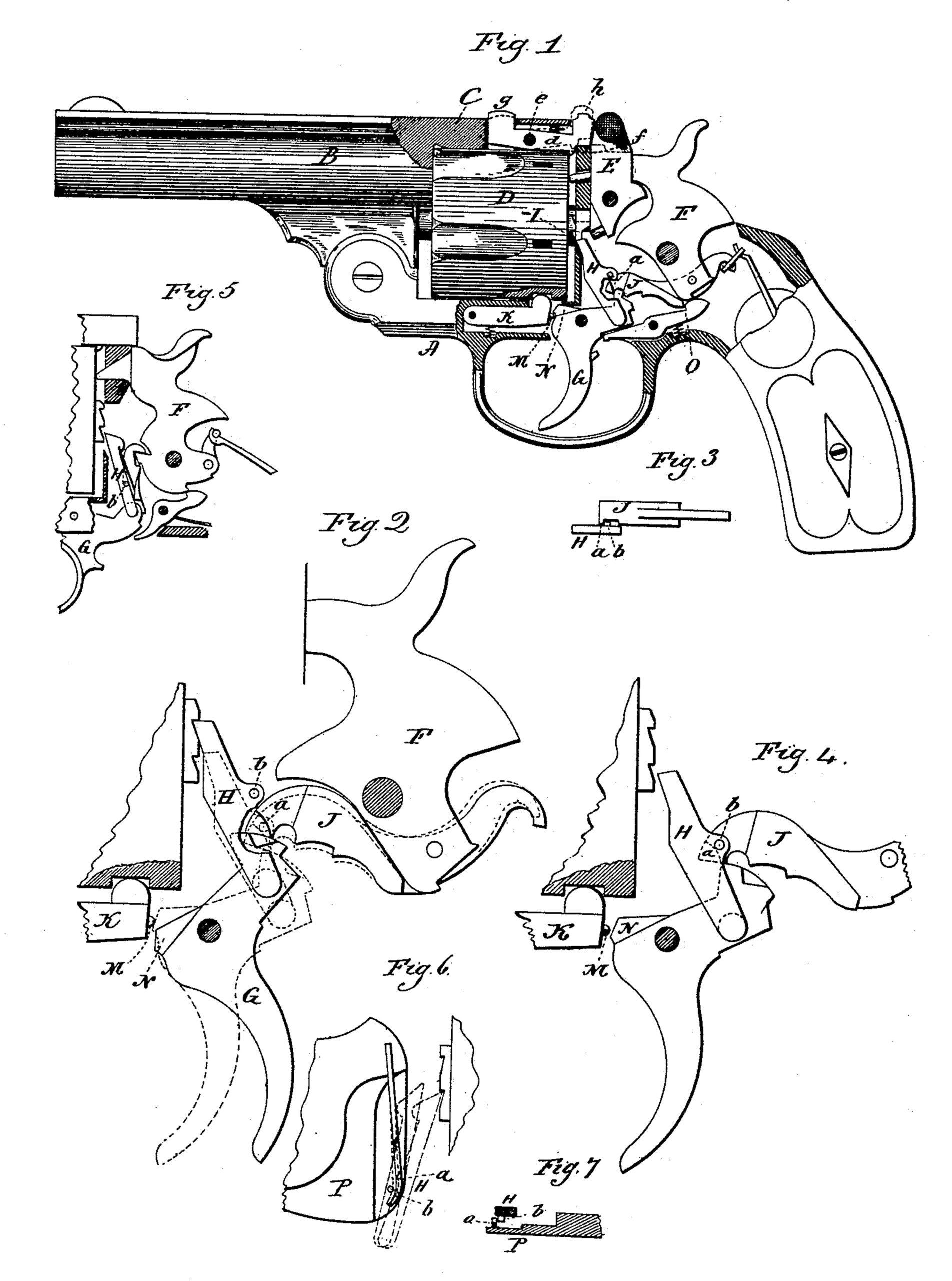
Figure 1, a sectional side view of a revolver illustrating the invention; Figs. 2, 3, and 4, detached views illustrating the operation of the invention. Figs. 5, 6, and 7 represent the invention as applied to a revolver of different construction from that shown in the preceding figures.
This invention relates to an improvement in that class of revolvers which are made self-cocking, parts of the invention, however, being applicable to revolvers which are not so self-cocking.
In self-cocking revolvers as more generally constructed the hand or pawl which imparts the rotative movement to the cylinder is hung directly to the trigger in rear of its pivot, and so that as the trigger is pulled backward the pawl rises and imparts rotation to the cylinder. Under the same movement of the pawl engagement is made with the hammer to throw it to full-cock; but it is necessary that the hammer shall start upon its rear movement before the cylinder commences its rotation; hence the pawl must descend to a point so far below the tooth of the ratchet with which it would next engage as to give an over motion to the pawl before it engages the tooth, during which over motion of the pawl the hammer will have been so far thrown back as to leave the heads of the cartridges in the cylinder free from contact with the nose of the hammer. The cylinder is necessarily locked after each rotation and before the hammer descends. In self-cocking revolvers this lock is made automatic, but is disengaged by the pull of the trigger, and the disengagement must be made during the over motion of the pawl which I have described. The engagement of the trigger with the cylinder-locking device is made during the last part of the forward movement of the trigger–that is, on the last part of the descent of the pawl. From this it follows that as the pawl commences its ascent the cylinder is locked, and unless the trigger has engaged the cylinder-locking device, so that it may throw it out of engagement with the cylinder, the pawl will engage the cylinder while it remains locked, the result of which will be that the pull of the trigger is prevented. The pawl, as I have stated, passes to some distance below the notch with which it is next to engage, and the trigger engages with the locking device substantially after the pawl has passed below the tooth with which it is to next engage. Now if the trigger be not permitted to reach its extreme forward movement, but only so far as to permit the pawl to escape from its tooth and the trigger be then pulled, the cylinder-lock will not have been disengaged. Consequently the cylinder cannot revolve, and under this pull the revolver will not operate.
The object of the first part of my invention is to avoid this difficulty by preventing the possible engagement of the pawl with the cylinder until the trigger has reached its extreme forward movement, so as to disengage the cylinder from its locking device; and it consists in introducing a cam over which a corresponding projection on the pawl must pass as it descends, and which projection will throw the pawl rearward and out of range of the ratchet on the cylinder until the extreme forward movement of the pawl is reached, and so that the cylinder-locking device will be engaged by the trigger before the pawl is brought into range with the cylinder-ratchet.
The object of the second part of my invention is to provide a simple and convenient device to yieldingly hold the cylinder in its forward position on its axle, and so that when the barrel and cylinder are turned away from the frame the cylinder cannot escape unless the said device be thrown out of engagement with the cylinder; and it consists in a latch hung in the arm which extends from the barrel over the cylinder, and so as to swing in a vertical plane independent of the latch which secures the said arm to the frame, the nose of the said latch in the arm being adapted to overlap the rear end of the cylinder, but from which it may be turned by a projection of the latch through the said arm, as more fully hereinafter described.
In illustrating my invention I show it as applied to a well-known revolver, in which A represents the frame; B, the barrel hinged thereto, with an arm, C, extending from its upper side rearward adapted to engage the frame at the rear of the cylinder-opening; D, the cylinder; E, the latch hung in the frame at the rear of the cylinder and adapted to engage the arm C: F, the hammer; G, the trigger; H, the pawl or hand hung to the trigger in rear of its pivot and adapted to engage the ratchet I on the cylinder; J, the dog hung to the hammer below its pivot and adapted to engage the trigger, so that while the dog is engaged with the trigger, as seen in Fig. 1, a pull of the trigger will throw the hammer to full-cock position, where it will be engaged by the sear.
K is the cylinder-dog, which is hung in the frame below the cylinder, its nose L adapted to enter a corresponding recess in the periphery of the cylinder. This dog carries a spring latch, M, which is arranged in the end of the said lever K, so that the nose of the latch will project from the end of the lever, as clearly seen in Figs. 2 and 4, the spring yielding so that the latch may be forced inward, but normally holds the nose of the latch projected, as represented. The spring is not shown, such a latch being a common and well-known device in revolvers, and the trigger has a corresponding cam, N, this cam forming a shoulder above the latch M when the parts are in their normal condition, as seen in Fig. 1, and so that as the trigger is pulled the said shoulder N will engage the latch M and draw the dog downward to release the cylinder, and this engagement of the trigger with the dog K occurs before the pawl H will reach its notch or tooth in the ratchet I of the cylinder, the nose of the pawl H. normally standing so far below the said tooth of the ratchet as to permit a sufficient movement of the trigger to disengage the latch before the pawl will engage the ratchet, all in a usual and well-known manner. After the trigger has been pulled to throw the hammer to full-cock and rotate the cylinder, as seen in Fig. 2, the latch M of the cylinder-dog K escapes from the shoulder N of the trigger, and under the action of its own Spring flies up, and its nose L enters a corresponding notch in the cylinder, so that the cylinder may be held while the hammer strikes. Upon the release of the trigger it must move so far forward that the shoulder N may pass above the latch N. In so doing the shoulder acts as a calm to force the latch inward until the shoulder has passed above the latch, and this engagement of the shoulder with the latch can only be made upon the extreme forward movement of the trigger, and the trigger must have a movement before the pawl H engages the ratchet of the cylinder sufficient to permit the shoulder N of the trigger to withdraw the nose L of the dog K from the cylinder. If the trigger moves only so far forward as to permit the pawl to pass over the next tooth of the cylinder-ratchet, but not so far as to permit the trigger to engage the cylinder dog, and the trigger be then pulled, the pawl will engage the cylinder while the cylinder is locked, and the trigger can move no farther, the operation being blocked.
To prevent the engagement of the pawl with the cylinder until such time as it shall be unlocked so as to rotate, I provide a cam which, after the pawl has risen to its extreme height, will engage the pawl and turn it rearward from the ratchet so far as to clear the tooth of the ratchet and hold it out of possible engagement with the cylinder until the trigger shall reach its extreme forward movement, and so as to certainly engage the cylinder dog. In the illustration, Fig. 1, this cam is formed on the dog J, and is represented at a, a portion of the pawl H being broken away in Fig. 1 to show this cam. On the pawl H a lateral projection or laterally-projecting stud, b, is formed, which is adapted to engage the cam a, as seen in Fig. 3. When the parts are in the normal condition or at rest, as represented in Fig. 1, the stud b stands above the cam a, and so as to be free to be thrown forward against the ratchet in the usual manner. At the same time the shoulder N of the trigger stands above the latch M of the cylinder-dog K. Now when the trigger is pulled the first operation is to draw down the dog K, so as to release the cylinder, and this occurs before the nose of the pawl H will have risen so far as to engage the next tooth of the cylinder. Then the pull is continued until the cylinder is turned to the next position. During this movement the latch M of the dog K has escaped from the shoulder N of the trigger and been thrown toward the cylinder, so that its nose will engage the next notch in the cylinder, as represented in Fig. 2. During this movement of the trigger the hammer has been thrown to full-cock through the engagement of the dog J with the trigger, and as the pull of the trigger is completed the hammer engages its sear O, the dog J escapes from the trigger, and the trigger trips the sear, so as to permit the hammer to escape and fly forward. The forward end of the dog J, as the hammer is thrown forward, rides over its engaging projection on the trigger, but still rests thereon, as seen in Fig. 2, leaving the cam a below the stud b on the pawl H, and the cam a in the path of the said stud b when the pawl next descends. Now the trigger is permitted to move forward, and as the pawl descends its stud b engages the cam a on the dog J, and is thereby forced rearward, as seen in Fig. 4, out of possible engagement with the ratchet. The dog J rides upon the trigger until just as the trigger completes its extreme forward movement, as represented in Fig. 4, and until after the shoulder N of the trigger has passed above the latch M of the dog K, as seen in Fig. 4. Now the dog J escapes over the projection on the trigger and drops to the position seen in Fig. 1, ready for the next engagement, and this dropping of the dog J releases the pawl and permits it to fly forward to engage the ratchet as the trigger is next pulled. If therefore the trigger be pulled before the dog J shall have so escaped from the trigger, the pawl H will simply move upward, but so far in rear of the ratchet as not to engage therewith, and the pull of the trigger may be completed without interruption.
The illustration which I have made of the calm to hold the pawl out of engagement with the cylinder until the cylinder shall have been unlocked is sufficient to enable others skilled in the art to apply the invention to other constructions of revolver; but to illustrate the possibility of such adaptation to other revolvers I represent the invention as applied to another construction of revolver in Figs. 5, 6, and 7, the same letters in these figures indicating corresponding parts. I need only refer to the pawl H, which is hung to the trigger G in the usual manner, and so as to engage the ratchet I on the cylinder. In this case the stud b is applied to the outside of the pawl H, and on the inside of the cheek P a spring-cam, a, is arranged, forward of which the stud b passes as the pawl rises, the spring cam yielding, as represented in Fig. 6, for such rise of the pawl. Then the cam flies into the path of the said stud in its descent, and so that as it descends the cam will throw the pawl rearward, as indicated in Fig. 6, and hold it out of engagement until the trigger has reached its extreme forward movement, so as to be able to release the cylinder on the next pull. The illustration of this modification represents the invention as applied to the well-known Smith & Wesson revolver.
To hold the cylinder in place when the barrel is turned from the frame, I introduce into the arm C a latch, d, hung upon a pivot, e, in the arm, and so as to swing in a vertical plane the rear end of the latch is constructed with a shoulder, f, which is adapted to set over the rear end of the cylinder, as seen in Fig. 1. In rear of the pivot the tail of the latch extends up through an opening in the arm and terminates in a thumb-piece, g, which projects slightly above the arm C, and so that, placing the thumb thereon, the latch may be turned upon its pivot, so as to throw the nose f out of engagement with the cylinder, as represented in broken lines, Fig. 1. The rear end of the latch extends up through a corresponding opening in the arm to form the back sight, h. The latch E, which holds the arm in engagement with the frame, is hung upon the frame and swings over the rear end of the arm C in the usual manner. The latch d, therefore, has no connection with the latch E, but is entirely independent of it, and one performs no office in Connection with the other.
I claim–
1. In a revolver, the combination of the cylinder, the locking-dog for the cylinder, the trigger, the cylinder-pawl and the ratchet on the rear end of the cylinder, the pawl constructed with a lateral stud or projection with a calm below said projection. On the pawl when the pawl is in its raised position, and over which the said projection will pass as the pawl descends, substantially as described, and whereby the said pawl will be thrown rearward during its descent and held out of engagement with the cylinder until the trigger reaches its extreme forward position.
2. In a revolver, the combination of the cylinder D, the hammer F, trigger G, pawl H, hung to the trigger, ratchet I on the cylinder, dog J between the hammer and trigger, and the cylinder-dog K, the said dog J constructed with a cam, a, and the pawl H with a corresponding lateral projection, b, and the trigger constructed with a shoulder, N, adapted to engage said dog K when in the normal position, substantially as and for the purpose described, and whereby the said cam a, through the said projection b, serves to throw the said pawl H out of engagement with the ratchet of the cylinder as the said pawl descends preparatory to a new engagement.
JOHN T. SMITH.
Witnesses:
SAMUEL L. WARNER,
HARRIS WARNER.