
US 22412
UNITED STATES PATENT OFFICE.
JNO. W. COCHRAN, OF NEW YORK, N.Y.
IMPROVEMENT IN REVOLVING FIRE-ARMS.
Specification forming part of Letters Patent No. 22,412, dated December 28, 1858.
To all whom it may concern:
Beit known that I, John W. Cochran, of the city of New York, in the county of New York and State of New York, have invented certain new and useful Improvements in Revolving Fire-Arms; and I du hereby declare that the following is a full and exact description thereof, reference being had to the accompanying drawings, and to the letters and marks thereon.
The fire-arms denominated “revolvers” are generally carried in a pocket of ordinary wearing apparel or in belts about the body. When so carried, as also when handled, liability to accidents exists by reason of the thumb-piece of the hammer or cock being caught in the lap of the pocket or coming in contact with some object, and thus being actuated produces a discharge of the contents of one or more of the barrels or tubes of the weapon. Liability to discharge also exists from the end of the hammer or cock resting fully upon the cap, when the weapon is carried loaded and capped, by the falling of the weapon upon the pavement or floor or coming in contact suddenly with any hard surface, whereby concussion is produced. One of the evils of this class of fire-arms, and for the overcoming of which many efforts have been made, is the uncertainty of having the revolving cylinder in the proper position for the fair hitting of the cap by the hammer when the discharge is desired, the holding of the cylinder truly and firmly at the termination of the movement of rotation and when the trigger is pulled for firing. It has been found very difficult in revolvers to so arrange the means for actuating the hammer and rotating the cylinder as to chamber them compactly and keep them free from dust and dirt, which is apt to accumulate in the chamber and upon the means named under ordinary exposure or ordinary use from carrying the weapon or from firing it. There are various reasons why the cylinder should be so placed and arranged upon the rod or shaft and within its frame that it may be taken out of the frame and from off the shaft, or rotated upon its shaft Within the frame independent of the cock-shaft readily and conveniently.
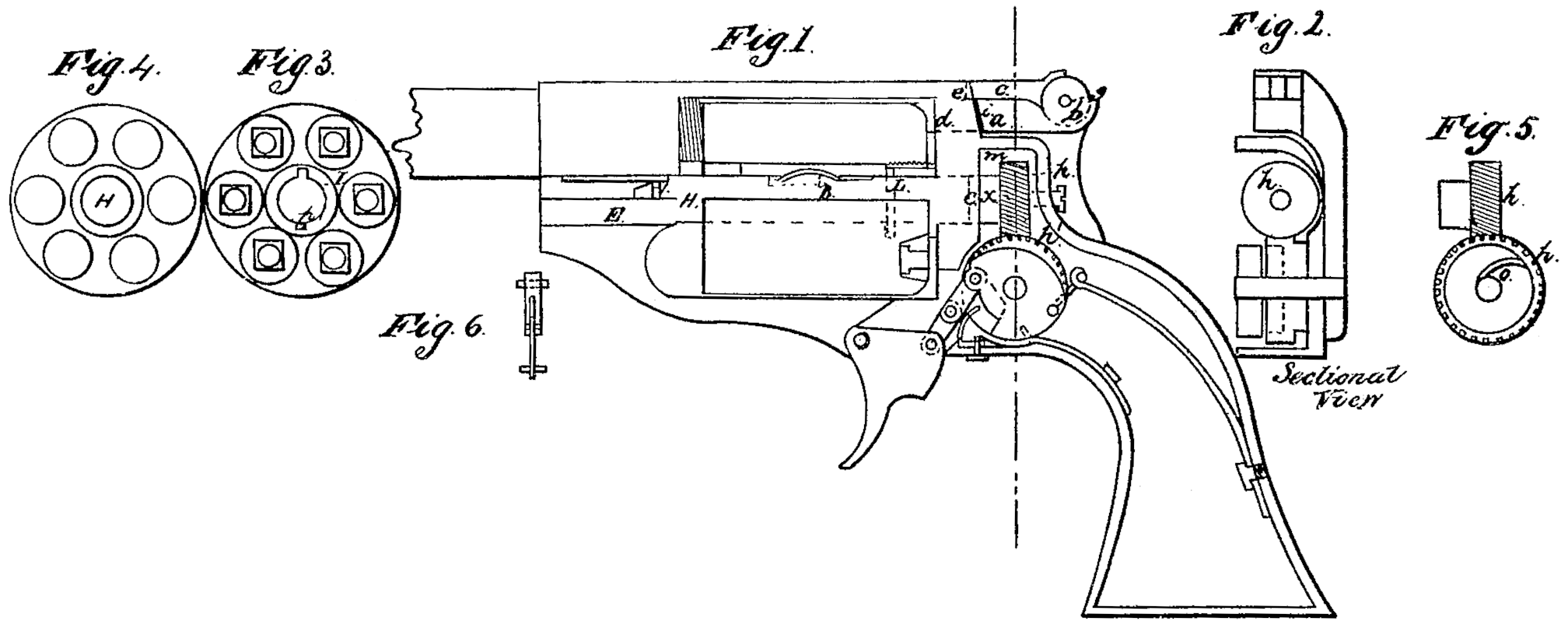
Of the drawings forming part of this specification, Figure 1 is a side view of a pistol or revolver with one side of the recess or chamber containing the devices or means for actuating the hammer and cylinder removed. Fig. 2 is a cross-section, as indicated by the red line in Fig. 1. Fig. 3 is a rear end view of the cylinder; Fig. 4, a front end view of the cylinder; and Fig. 5, a view of the two worm-wheels, the one being attached to the short part of the shaft of the cylinder and the other attached to the cock or tumbler shaft. Within the last named is shown the pawl for controlling the rotation of the wheel. A slide and yoke for compressing a forcing-spring placed at the front end of the cylinder-shaft and for drawing out the end of that shaft is shown by Fig. 6.
In getting up my improvements I have had in view providing for the wants here specified on the one hand and remedying the evils briefly alluded to on the other hand.
To obviate the evil first named— the catching of the thumb-piece of the hammer— I make the thumb-piece hinged to the rear part of the hammer or cock, so that when needed to be used it will stand perpendicular, or nearly so, to the top of the hammer, and when not needed will lie close down upon the top of the hammer, and there be held in position, presenting no prominence for catching or contact, as here in before named. This feature of my improvements will readily be seen by examining Fig. 1 of the drawings. The hammer or cock is here lettered a ; the hinge or joint of the thumb piece b, the thumb-piece c. The front end of the hammer— that which strikes the cap— is shown by dotted lines, and marked d. The front end of the thumb-piece is slightly beveled, and fits into a slightly-beveled recess in the end of the frame e. The action of the mainspring upon the hammer or cock, when the hammer is thrown forward, is to keep this edge of the thumb-piece in the recess. As the hammer is pressed upon by the thumb, as in the act of cocking, or moved by the pull on the trigger when the trigger is made to elevate the hammer, the thumb-piece is, by the action of a spring fitted in a recess in the top of the hammer, thrown upward and into position for pressure by the thumb to cock the hammer. When the cocking is performed by the thumb instead of by the trigger, if the first joint of the thumb be placed directly over the joint of the thumb-piece, a slight force will liberate the beveled edge of the thumb-piece from the recess, and the ball of the thumb will have full bearing upon the front end of the thumb-piece, so that the act of cocking will be very easily and surely performed.
To prevent the end of the hammer from pressing upon the cap when the weapon is carried loaded and capped, I make the thumb-piece a little longer than that part of the hammer which lies between the shoulder of the hammer i and the hinge-pivot of the thumb-piece g. By doing this the end of the hammer will not come in contact with the cap and the thumb-piece is more surely held in the flat position, as it is then under the entire force of tle main spring.
In order to hold the cylinder in a firm position after its rotation and during the act of firing, I use a worm-wheel upon the cock or hammer shaft and a like wheel upon the cylinder-shaft. h h’ indicate these worm-wheels, the latter, h’, being so arranged on the hammer-shaft with the spring-pawls o that it can only revolve one way. By the use of the worm wheels the use of the dog for holding the cylinder can be avoided, and, as will be seen, the entire means for operating the cylinder and hammer be compactly arranged within the recess, and be kept wholly free from dirt and dust.
The manner in which I arrange my cylinder shaft and cylinder allows me to dispense with the worm-wheels, and yet retain the compact condition of the devices or means for actuating the hammer and rotating the cylinder.
Instead of the worm-wheel in the short shaft x, a ratchet-wheel may be upon that shaft, and then, by a pawl attached to the tumbler or cock shaft, the cylinder may be rotated, and the cylinder then may be held by a dog or by any ordinary means.
In carrying into practice that important part of my improvement which relates to the ready and convenient detaching of the cylinder from its frame and, if necessary, from its shaft, I adopt the following plan: The shaft of the cylinder is made up of two pieces, the longer, H, mostly within the cylinder, and the shorter, x, mostly within the chamber m, and to which is attached the worm-wheel h. These two parts of the shaft are connected by a clutch, c, (shown by dotted lines,) within the recoil-plate. The forward end of the first-named part of the shaft is fastened by a yoke to a slide, E, in the frame, a coiled spring being affixed to the yoke and so arranged in a recess in the frame that its tendency is to keep the two parts of the shaft coupled or clutched. The yoke fits into a groove, 1, on the end of the shaft, and thus by the movement of the slide the spring may be compressed, the two parts of the shaft be unclutched, the shaft be liberated from the yoke, and the cylinder and longer part of the shaft be removed from the frame. This arrangement also allows of the cylinder being rotated while on its shaft and within the frame. The longer part of the shaft H is connected to the cylinder by a feather, L, on the shaft, which fits into a slit or groove, p, in the packing-ring I. (Shown best by Fig. 3 of the drawings.) A flat spring, B, upon shaft H, serves, by friction, to steady the cylinder upon the shaft when unclutched and to keep the shaft in the cylinder when detached from the frame.
It will readily be perceived that by a forward movement of the slide E the longer part of the shaft may be unclutched from the shorter part and the cylinder have free motion within its frame, the rear end of the shaft being within the recoil-plate and the front end of it within the recess in the front part of the frame.
A coiled spring may be used on the shaft within the cylinder, so as to draw the shaft out of gear when the forcing-spring is drawn back in front, the latter of course being the strongest, so as to be sure to keep the shaft safe in gear or clutched. The spring on the shaft will have no function except to overcome the light friction of the shaft; and then I avoid the use of a draw-back pin and the small spring to keep it out when not in use in connection with the slide and yoke.
Having thus fully set out the construction and operation of my invention, what I claim as new, and desire to secure by Letters Patent, is—
1. The hinged or jointed thumb-piece of the hammer or cock, constructed and arranged and having the functions substantially as herein set forth.
2. The worm-wheels upon the cylinder-shaft and the tumbler-shaft or hammer-shaft, combined and operated as and for the purposes described.
3. The means, substantially as herein set forth, for allowing the cylinder to be rotated within its frame independent of the shaft of the hammer or tumbler, and also allowing of the detaching of the cylinder and its shaft from the frame and from the means for rotation.
J. W. COCHRAN.
Witnesses:
A. B. Howe,
W. H. LaBoyteaux.