
US 21730
UNITED STATES PATENT OFFICE.
THOMAS K. AUSTIN, OF NEW YORK, N.Y.
IMPROVEMENT IN REVOLVING FIRE-ARMS.
Specification forming part of Letters Patent No. 21,730, dated October 12, 1858.
To all whom it may concern:
Be it known that I, Thomas K. Austin, of the city and State of New York, have invented and made certain new and useful Improvements in Repeating Fire-Arms; and I do hereby declare that the following is a full, clear, and exact description of the construction and operation of the same, reference being had to the annexed drawings, making part of this specification, wherein—
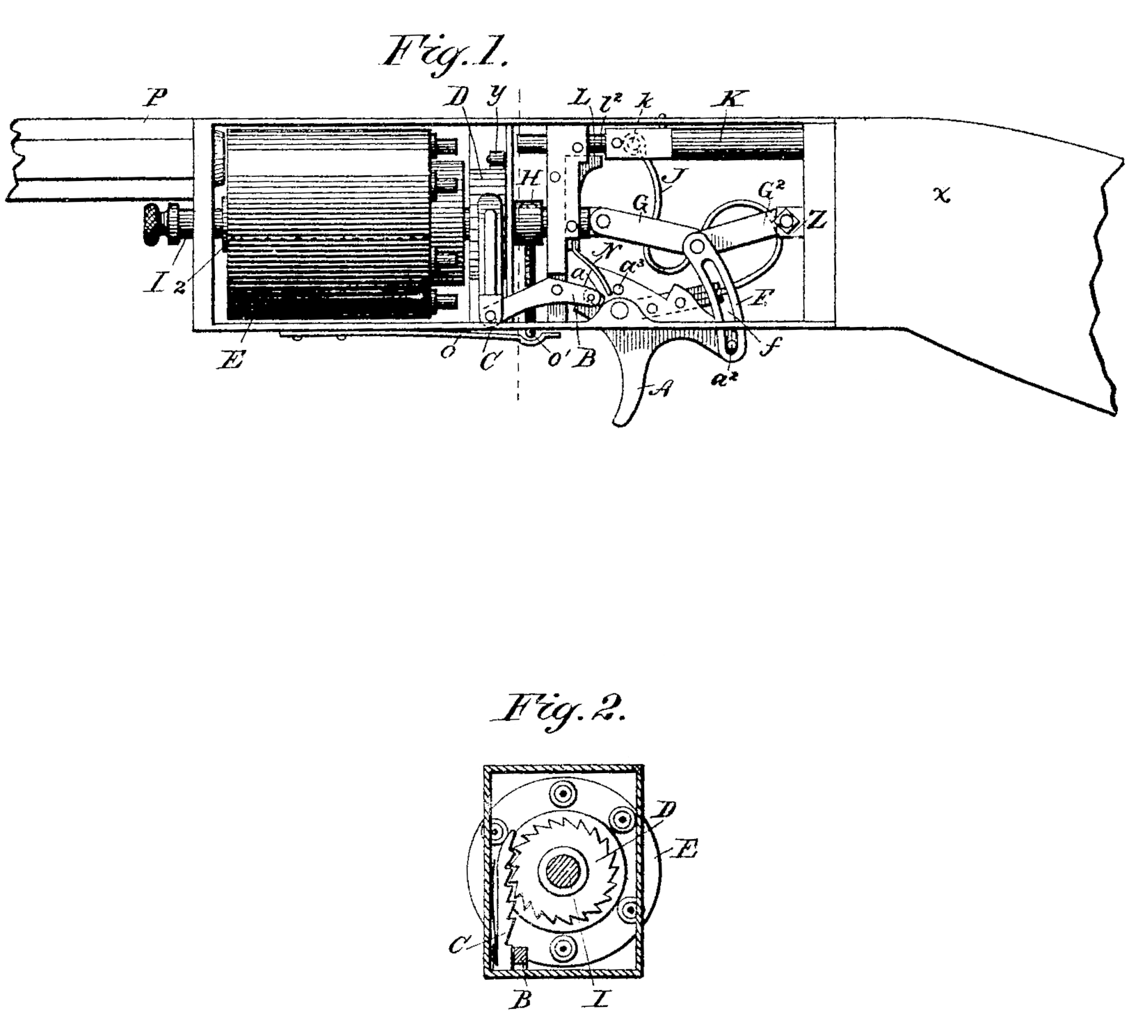
Figure l is a side view of my repeating-pistol, and Fig. 2 is a cross-section at the rear of the revolving ratchet.
Similar marks of reference indicate the same parts.
The nature of my said invention consists, first, in a manner of applying the mainspring on or as a part of the trigger; second, in an arrangement of sliding center-pin, latch, and toggle-joint, whereby the chambers are successively pressed to and withdrawn from the rear end of the barrel; third, in the arrangement of a double-acting return spring to cock the hammer and restore the parts to their previous position.
In the drawings, the barrel P and stock a are to be of any desired construction, connected by the straps, as usual.
E is the revolving chamber on the pin I, and the mouth of each chamber or breech is made flaring or conical, sitting over a corresponding conical rear end of the barrel P, so that the chambers, being rotated and receiving an end wise motion, simultaneously make a tight joint between the chamber and the barrel, and bring said chamber properly into a central position to the barrel, and there locks the same. The end wise motion to said cylinder is effected by providing a shoulder on the pin I at 2 and a recoil-shield, H, on the end of a second pin, H’. The pin I enters the shield H, to which it is connected by the bolt o’, acted on by the spring o and shackle o^2, so that by withdrawing the pin o’ and the center-pin I the cylinder E can be removed; but the giving of motion endwise in either direction is accomplished by acting on the pin H’ by means of the toggle joint G G^2.
Z is the fixed end of the toggle-joint, and F is an arc, connecting from the center of the toggle joint to the trigger A.
a^2 is a pin on the rear end of said trigger, traveling in a slot, f, in this arc F, which allows the trigger to perform the other duties hereinafter designated, and then act on the toggle-joint and force the cylinder E, with the upper breech or chamber, tightly to the rear end of the barrel P.
J is the main spring, formed on or connected to the trigger A. This spring is of an S shape or other convenient farm, and the end thereof terminates as a roller k, in a slot in the hammer K.
L, is a detent or sear taking into a notch at l^2 in the hammer K. This sear L retains the hammer in a retracted position until the pull on the trigger A has strained and produced a propelling power from the mainspring J, and as the trigger A completes its motion and the toggle-joint G. G’ is brought into a straight line the sear L is removed by a finger, 4, on the toggle-joint, and the hammer K is propelled against the cap to explode the chamber on line with the barrel. The parts are returned to their former position by the mainspring J, in conjunction with the spring N, which latter is set on a pivot or screw, 3, and is double-acting, one end acting on the pin a^3, returning the trigger A, toggle, mainspring J, hammer K, and cylinder E, and the other end returns the sear L to the notch l^2 in the hammer K.
The rotation of the cylinder E is effected by the slot a of the trigger A acting on the pin of a lever, B, the forward end of which carries the rack-ratchet C, kept to the teeth of the wheel D by a spring; and y is a retaining pawl to prevent any back motion to the cylinder E. The peculiar advantage of this ratchet rack is that, the number of teeth being two or three times that of the chambers, the rack is uniform in its operation, always acting with the same leverage on the cylinders, making a smoother motion and avoiding the variation of leverage consequent upon the use of the ordinary rotating pawl.
My improvements may be applied to any character of fire-arm to which they are adapted.
What claim as my invention, and desire to secure by Letters Patent, is—
1. The mainspring J, attached to or formed on the trigger A, substantially as specified, whereby the pull on said trigger strains the main spring, as set forth.
2. The sliding center-pin I, shield H, pin H’, and toggle joints G G^2, when combined with the latch o’ for disconnecting the pin I, as described and shown.
3. The double-acting spring N, fitted and acting, as specified, to return the sear L and trigger A and parts attached to their quiescent position, as set forth.
In witness whereof I have here unto set my signature this 6th day of September, 1858.
TEHOMAS K. AUSTIN.
Witnesses:
Lemuel W. Serrell,
Thomas G. Harold.