
US 357085
UNITED STATES PATENT OFFICE.
IVER JOHNSON AND ANDREW FYRBERG, OF WORCESTER, MASSACHUSETTS; SAID FYRBERG ASSIGNOR TO SAID JOHNSON.
REVOLVER.
SPECIFICATION forming part of Letters Patent No. 357,085, dated February 1, 1887. Serial No. 212,092. (No model.) Application filed August 28, 1886.
To all whom it may concern:
Be it known that we, IVER JOHNSON and ANDREW FYRBERG, both of Worcester, in the county of Worcester and State of Massachusetts, have invented certain new and useful Improvements in Fire-Arms; and we do hereby declare that the following is a full, clear, and exact description of the same, reference being had to the accompanying drawings, forming a part of this specification, and in which–
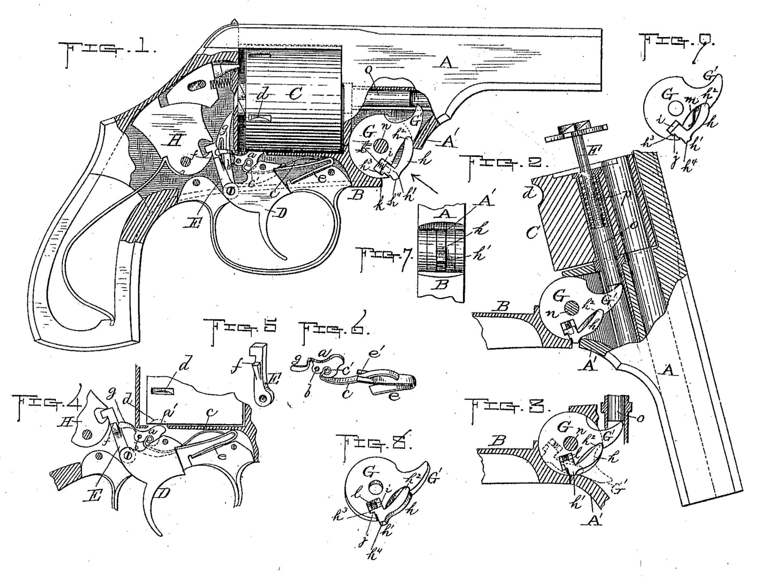
Figure 1 represents a side view, partly in section, of a revolver with our improvements applied thereto; and Figs. 2 to 9, inclusive, represent different details of the parts of said revolver embodying our improvements.
Our invention relates to the cylinder-holding and cartridge-extracting mechanisms of a fire-arm; and it consists in combining with the usual cylinder-stop a spring and arm so formed and arranged as to operate said stop to unfasten and fasten the cylinder by the operation of the “raiser,” and of combining with the extractor-disk of said arm a spring-lever having a shoulder adapted to bear against the forward end of the fore-hand, whereby when the barrel is swung or dropped down, as usual, the cartridge-extractor is forced forward to extract the cartridge-shells, as hereinafter specified.
To enable those skilled in the art to which our invention appertains to make and use the same, we will now proceed to describe it more in detail.
In the drawings, the part marked A represents the barrel; B, the fore-hand; C, the cylinder; D, the trigger; E, the raiser; F, the cartridge-extractor, and G the cartridge-extractor disk.
Our improved cylinder-stop is constructed and arranged to be operated in the following manner: The part a represents said stop, which is pivoted at b to the frame of the revolver. To the under forward end of said stop is fastened in any suitable way a spring, c, for forcing up and holding the part a’ of the stop in one of the notches d of the cylinder, as shown in Fig. 1. In this instance said spring is held in the stop by forming a circular recess or slot in the stop to receive and hold the bent eye-shaped end c’ of the spring. An upward pressure is produced upon it by the trigger-spring e, said spring c being extended forward from the cylinder-stop through a slot, e’, in said trigger spring, and thence over the latter, as shown in Figs. 1, 4, and 6.
By the above construction and arrangement it will be seen that the combined action of the springs c and e produces a constant upward pressure to hold the cylinder-stop in its normal position, engaged with the cylinder C. It is disengaged therefrom to allow the cylinder to be turned, by pulling back the trigger D from the position shown in Fig. 1 to that shown in Fig. 4, said operation causing the usual raiser, E, to be forced up, so that a shoulder, f, formed or secured thereon will come in contact with and force up an arm, g, extend ing back from the cylinder-stop a. In thus forcing up the raiser E, the shoulder f first comes in contact with the under side of the end of the arm g aforesaid. Then, as said raiser is continued to be forced up and back in the operation of raising the hammer H, the notch passes beyond the end of the arm and the latter bears against the forward side of the projection forming the shoulder f, until it arrives at the bottom thereof, (by the continued upward movement of the raiser,) when said arm, being released from the counter pressure of said projection against that of the springs c and e, allows the latter to force the stop into its normal position, with its upper curved part a’ engaged with one of the holding-notches d of the cylinder C, as hereinbefore described.
The essential feature of this part of our improvements consists in operating the cylinder stop of a fire-arm by means of its hammer raiser, and we therefore do not limit ourselves to the particular construction and arrangement previously set forth and shown for effecting said result.
Our improved cylinder-stop is timed to operate in connection with the cylinder and other adjacent parts, as in other fire-arms whose stops are operated by other means than those herein shown and described, being moved out of its holding-notch in the cylinder to unlock the same just prior to its being turned in the usual way, and then up to again lock the same after having been thus turned into position for firing.
Our improvements in the cartridge-extractor mechanism relate particularly to the extractor-disk, upon which is formed the finger G’, for forcing out the usual extractor, F, to extract the empty cartridge-shells, and consists in combining with said disk a lever, h, having a head, h’. The disk is recessed or cut out upon its under forward side to receive the lever h. The plain end h2 thereof fits against a shoulder formed in the disk at the base of the extractor-finger G’, while its head h’, which is provided with a holding-lip, h3, is fitted in a recess, i, formed in the bottom of the disk, said lip h3 holding against the internal shoulder, j, formed on the disk. The lever is held in position from falling out by said lip h3 at one end and the part A’ of barrel A at its other end, in connection with the shoulder at the base of the finger G’, and is provided upon the outer side of its base end or head h’ with a projection, h4, made square upon its back side to form a shoulder for the end k of the fore-hand B to bear against when the lever is swung around, as hereinafter specified, and curved or beveling upon its front side, for the purpose also hereinafter described.
A constant outward pressure is exerted against the inner side of the lever-head, h’, to keep it in its normal position, as shown in Figs. I and 8, by means of a spring, l, interposed between said head and the bottom of the recess in which it is fitted, or in any other suitable and convenient manner–as, for instance, a flat spring may be placed between the part in of the disk and the body or central part of the lever, as shown in Fig. 9, to produce the same result.
The operation of our improved cartridge-extractor disk in connection with the old parts of a fire-arm is as follows: Assuming that the various parts are in their normal positions, as shown in Fig. 1, and all the cartridges have been exploded ready to extract the shells thereof, the barrel is first unlocked from the frame in the usual way and then swung or dropped down on its pivot n into the position indicated in Fig. 2. Said operation causes the disk G and its finger to be turned also (with the finger against the inner end of the extractor-spindle o) until the shoulder formed by the projection h4 of lever h comes in contact with the end of the fore-hand. The leyer now being held rigid against said bearing k as the barrel is further turned down, the finger bearing on the end of the extractor-spindle, as above stated, causes the latter to be forced out of the cylinder C, as shown in Fig. 2, and thereby extracting the cartridge-shells, as usual. In swinging the barrel down, when the part A’ thereof comes in contact with the curved or beveled front side of head h’ the lever h is forced back into the position shown in Fig. 3, thereby releasing the disk, so that it may turn upon its pivot n. Immediately upon the head h’ being forced back, as aforesaid, beyond its holding part k, the spring p of the extractor forces the extractor-spindle in, and in consequence turns the disk back into its normal position. (Shown in Fig. 1 and by dotted lines in Fig. 3.) The arm is now reloaded by inserting new cartridges and the barrel swung up and locked in position ready for firing.
Having described our improvements in fire-arms, what we claim therein as new and of our invention, and desire to secure by Letters Patent, is–
1. The combination of the hinged hammer-raiser E, having the inclined lateral projection f upon the face thereof, with the cylinder-stop a, hinged at b to the frame of the revolver and having a spring, c, or its equivalent, for forcing up its forward end, also provided with a rear projecting arm or lever, g, adapted to engage with the top and front side of the inclined projection f aforesaid, whereby, when the raiser E is moved up and back in lifting the hammer, by pulling upon the trigger the front end of the stop is depressed or forced down out of the cylinder-notch coming in line therewith, the arm g being released and the stop a thereby go allowed to assume its normal position upon said arm reaching the bottom of the inclined projection f, substantially as shown and described.
2. The extractor-disk G, pivoted at n and provided with the projection or finger G’, also with the lever h, having a bearing at one end at the base of said finger G’, and at its other end provided with a head or enlargement, h’, arranged and held in a recess, i, and the spring l,interposed between the bottom of said recess and head, in combination with the shoulder k on the fore-hand and the inner end of the extractor-spindle o, substantially as and for the purpose set forth.
IVER JOHNSON,
ANDREW FYRBERG.
Witnesses:
ALBERTA. BARKER,
ADELBERT F. MOWRY.