
US 339301
UNITED STATES PATENT OFFICE.
IVER JOHNSON, REINHARD T. TORKELSON, AND ANDREW FYRBERG, OF WORCESTER, MASSACHUSETTS; SAID TORKELSON AND FYRBERG ASSIGNORS TO SAID JOHNSON. REVOLVER.
SPECIFICATION forming part of Letters Patent No. 339,301, dated April 6, 1886.
Application filed January 4, 1886. Serial No. 187,558. (No model.)
To all, whom, it may concern:
Be it known that we, IVER JOHNSON, REINHARD T. TORKELSON, and ANDREW FYRBERG, all of the city and county of Worcester and Commonwealth of Massachusetts, have invented certain new and useful Improvements in Fire-Arms; and we do hereby declare the following to be a full, clear, and exact description of the same, reference being had to the accompanying drawings and letters of reference marked thereon, forming a part of this specification, and in which–
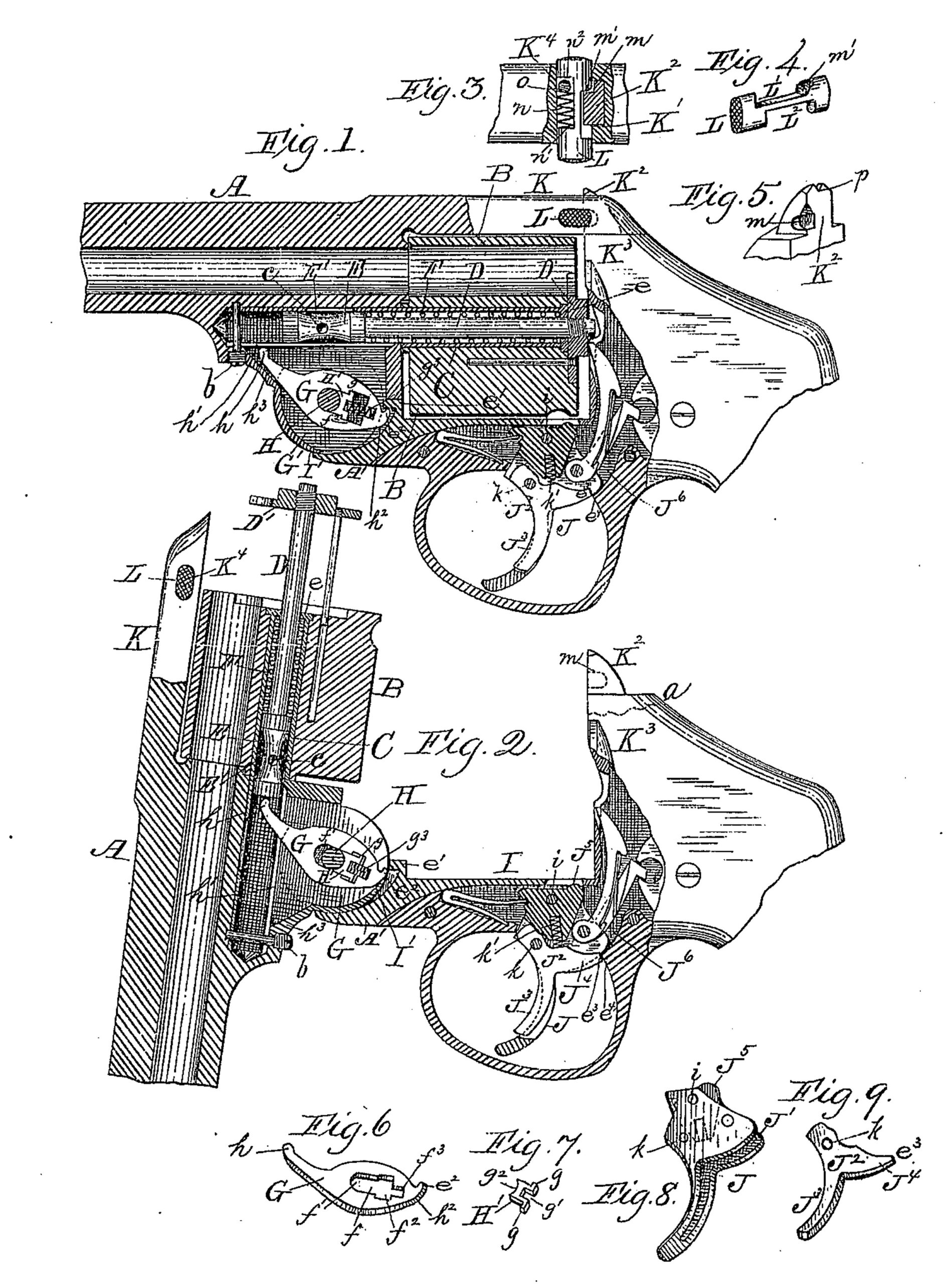
Figure 1 represents a side view, partly in section and partly in full lines, of so much of a revolving fire-arm as is necessary to illustrate our present invention, as will be hereinafter described. Fig. 2 represents a side view of the same parts shown in Fig. 1, with the trigger, its support, and rear portion of the arm shown in Fig 1 turned down as it appears when the ejector is operated to eject the cartridge-shells. Fig. 3 represents a top view of a portion of the top strap by which the breech and rear part of the arm are locked to the barrel, a portion being broken away, as shown in section, to illustrate the locking devices more fully. Fig. 4 represents a perspective view of the sliding notched locking-piece, as will be hereinafter described. Fig. 5 represents a perspective view of a portion of the breech-piece broken off on dotted line a, Fig. 2, and turned around to the right to show its construction more fully. Figs. 6, 7, 8, and 9 represent perspective views of detached parts, as will be hereinafter more fully described.
To enable those skilled in the art to which our invention belongs to make and use the same, we will proceed to describe it more in detail.
In the drawings, the part marked A is the rear portion of the barrel, shown in section.
B is the cylinder, fitted to turn on sleeve C, held in place by means of the screw-pin b. Sleeve C also receives and supports the ejector rod D, and which rod is provided with a spider, D’, on the outer end, and with a shoulder or hub part, E, at its other end, the ends of said shoulder part E being made to fit easily the inner surface of the sleeve C, while the center part, E’, is turned down in the form of a double cone, with a hole, c, in the smaller so part, as fully indicated in Figs. 1 and 2 of the drawings.
Against the right-hand end of shoulder part E one end of a spiral spring, F, presses against the inner flange, e, of the sleeve C, and the action of Spring F is such as to keep the ejector rod D and its spider D’ in their normal positions, as shown in Fig. 1, when not acted upon by the ejector finger or lever G, which is arranged in a slot or chamber, G’, in the rear under portion, A’, of barrel part A.
Ejector-lever G is provided with a slot, f, the upper part, f’, being rounded to receive the pivot H, upon which the forearm I turns when lowered to throw out the ejector-rod D and its spider D’. Slot f is enlarged at f2 and contracted at f3 at the bottom, the large part f2 being adapted to receive the flanges g g of the cap-piece H’, which in turn has a narrow slot, g’, at its lower end and a concavity, g2, to at its upper end. Concavity g2 fits pivot H, while one end of a small spiral spring, g3, fits in the narrow slot g’, the other end of spiral spring g3 fitting in the slot f3 of lever G.
The office of ejector – lever G is to throw out the ejector-rod D, and the operation is as follows: When the forearm I is turned down, lever G turns with it, being forced to turn by the flange or projection e’ on the forearm I striking against its lip e2, and as lever G continues to turn its point h, passing through a slot, h’, in the lower side of the sleeve C, strikes the inner end of the shoulder-piece E and forces out the ejector-rod and its spider, as indicated in Fig. 2, thereby ejecting the cartridge-shells.
I’ is a stationary cam, against which the beveled end h2 of lever G strikes, and said lever is pressed up as forearm I is lowered, until its lip e2 has been moved out of contact with projection e’, (see Fig. 2,) when the expansive force of spring F throws ejector-rod D and lever G back to their normal positions. (Shown in Fig. 1.)
As forearm I is turned back to the position shown in Fig. 1 projection e’ comes in contact with the outer curved surface of lip e2, when spring g2 and yielding lever G moves lengthwise and projection e’ is carried or moved beyond lip e2, after which spring of forces lever G, so that its lip e2 will again be under projection e’. (See Fig. 1.) Flanges g g on the cap-piece H’ come in contact with shoulders in lever G, thereby preventing cap piece H’ from rising so far as to obstruct the passage of pivot H. The narrow end of lever G coming in contact with the stationary part h3, its back motion is arrested, when it is thrown back by the action of spring F, through ejector-rod D, and also when projection e’ strikes the back of lip e2, when the forearm is returned to its locked position, and by which latter operation lever G is forced longitudinally until its lip e2 has passed projection e’, when lever G, by the action of spring g3, moves back and its lip e2 enters the pocket under projection e’, the latter forming the top thereof.
Trigger J is pivoted at i to the forearm I, and it is also provided with a slot, J’, in which the trigger-locking lever J2 is pivoted at k, and said locking-lever has a finger-arm, J3, and a locking-arm, J4.
J5 is the cylinder-stop.
From slot J’ extends a hole to receive the spiral spring k’, the lower end of which spring rests on the locking-arm J4 of trigger-locking lever J2, thereby keeping arm J4 down, as shown in full lines, Fig. 2, and in which position its end e3 will strike against the trigger-guard at e4, thereby locking trigger J, which cannot be moved accidentally or otherwise to fire the arm until arm J3, of trigger-locking lever J2 has been drawn back far enough to elevate the end e3 of its arm J4 above the point e4 of the trigger-guard, as indicated in Fig. 1 of the drawings, after which arm J4 moves with the rear upper part of trigger J up into chamber J6 in firing the arm. By this arrangement accidental firing of the arm is prevented, and that, too, in a simple and convenient manner. The same motion of the finger necessary to fire the arm also unlocks the trigger J; consequently extra motions are avoided.
By interposing cap-piece H’ between pivot H and spring g3 a free hole through the movable lever G is always preserved, whereas without the cap-piece, if lever G should be removed spring g3 would spring up into the hole previously occupied by pivot H, and the latter could not be conveniently inserted again, while there would be liability of injuring the spring by the operation.
The top strap, K, (shown partly in section in Figs. 1 and 2,) is provided with two slots or openings, said slots intersecting each other at right angles. The vertical slot K’ receives the projection K2 (shown in section, Fig. 3) of the breech part K3, connected with forearm I. Projection K2 is provided on its right hand side with a notch, m, to receive the shoulder m’ of locking thumb-piece L, which passes through the horizontal slot K4 in the top strap, K.
Thumb locking-piece L is provided with two notches-one, L’, to receive projection K2 of the breech part K3, and the other, L2, to receive spiral spring n and holding-pin o– and these parts are combined together as follows: Spiral spring n is arranged horizontally in notch L2, with one end resting against one shoulder, n’, of thumb-piece L, while the other end presses against holding-pin o, inserted in a vertical hole in strap K, so as to stand or abut against shoulder n2 of thumb-piece L, thus holding both spring n and thumb locking piece L in their proper relative positions, as fully indicated in Fig. 3.
The operation of this part of our invention is as follows: When forearm I is turned up, projection K2 enters the vertical slot K’, and, pressing against shoulder m’ on thumb-piece L, forces the latter to the right until notch m comes opposite shoulder m’ on thumb-piece L, when the latter is forced to the left by the action of spring n, thus bringing its shoulder m’ into notch m in projection K2 and locking the parts securely together.
To unlock the parts it is only necessary to press locking-piece L to the right far enough to disengage the shoulder m’ from notch m in projection K2.
Upon the breech part K3 is constructed the member K2, which extends upward through the strap K and forms the rear sight, p, as clearly shown in Fig. 5.
This method of construction is more simple, durable, and less expensive than has been hitherto employed on revolvers constructed upon the breakdown or tilting principle.
We are aware that rear sights have been constructed upon the stationary frame of revolvers, but not on those of the breakdown or tilting principle.
Having described our improvement in fire-arms, what we claim as new and of our invention, and desire to secure by Letters Patent, is–
1. The combination, with the lock mechanism of a fire-arm and firing-trigger hinged to the forearm, of a firing-trigger-locking lever, J2, pivoted in the firing-trigger below the firing-trigger pivot, and spring k’, arranged in a hole in the upper part of the firing-trigger, the lower end of said spring pressing down upon the upper edge of arm J4 of trigger-locking lever J2, and in rear of its pivot k in the firing-trigger, substantially as described, and for the purpose set forth.
2. The combination, with ejector-rod D, stationary cam G’, and hinged forearm I, provided with projection e’, which forms the top of a pocket for the reception of lip e2, of slotted lever G, provided with lip e2, to engage with projection e’, pivot H, upon which both forearm I and lever G turn, flanged cap H’, to fit the slot in lever G, pivot H, and spring g3, for keeping lip e2 in position to engage with projection e’, and movable lever G, to throw out ejector-rod D to eject the cartridge-shells when forearm I is turned down, substantially as described.
3. The combination, with strap K, provided with a transverse slot, K4, and slotted projection K’ on breech part K3, of the notched locking thumb-piece L, arranged in transverse slot K4, spring n, and holding-pin o, substantially as and for the purposes set forth.
IVER JOHNSON,
REINHARD T. TORKELSON,
ANDREW FYRBERG.
Witnesses:
THOS. H. DODGE,
HENRY L. MILLER.