
US 362632
UNITED STATES PATENT OFFICE.
IVER JOHNSON AND ANDREW FYRBERG, OF WORCESTER, MASSACHUSETTS; SAID FYRBERG ASSIGNOR TO SAID JOHNSON.
REVOLVER.
SPECIFICATION forming part of Letters Patent No. 362,632, dated May 10, 1887. Application filed January 21, 1887. Serial No. 325,276. (No model.)
To all whom it may concern:
Be it known that we, IVER JOHNSON and ANDREW FYRBERG, both of Worcester, in the county of Worcester and State of Massachusetts, have invented certain new and useful Improvements in Fire-Arms; and we do hereby declare that the following is a full, clear, and exact description of the same, reference being had to the accompanying drawings, forming a part of this specification, and in which–
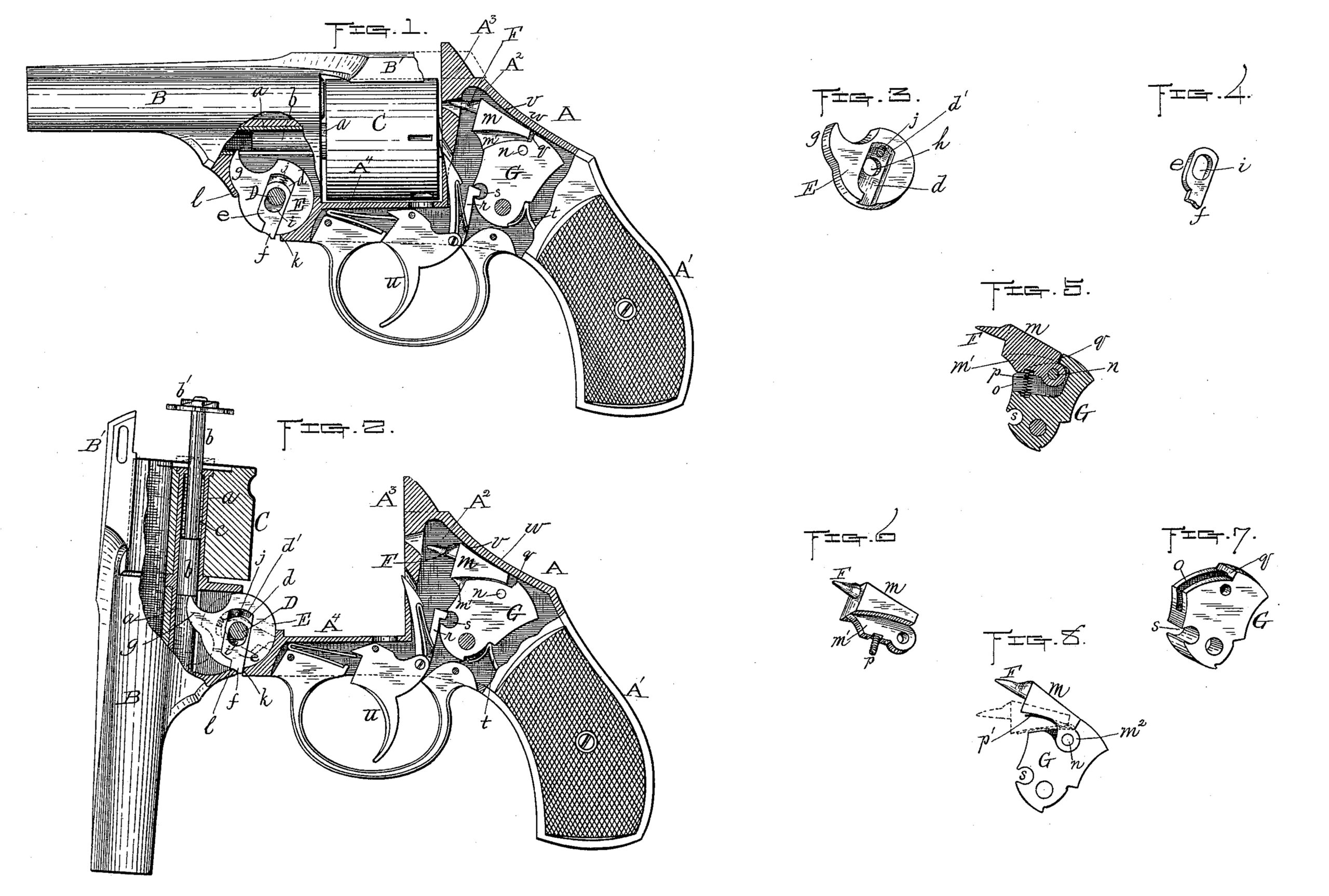
Figure 1 represents a side view of a revolver embodying our improvements, portions thereof being broken away to uncover and show said improvements more fully. Fig. 2 is a similar view of the revolver with the barrel unlocked and swung down and the trigger partially pulled back to more clearly illustrate the operation of the parts to which our improvements relate. Figs. 3 to 7, inclusive, are different views in detail of our aforesaid improvements, hereinafter more fully described; and Fig. 8 represents a modification in the method of supporting and operating the firing-pin, which will also be hereinafter described.
Our invention relates to breech-loading fire-arms having a revolving cartridge-cylinder, cartridge-extracting mechanism, and a concealed hammer, and more especially to the extractor-disk and firing-pin thereof. It consists in improvements in the construction of said extractor-disk and firing-pin, and the combination of the latter with the hammer of the fire-arm, as hereinafter more fully set forth.
To enable others skilled in the art to which our invention appertains to obtain a full and clear understanding thereof, we will now proceed to describe it more in detail.
In the drawings, the parts marked A represent the frame of the revolver, which comprises the handle A’, the receiver A2, the breech or bridge A3, and the fore-hand A4. The barrel B is provided with the usual top strap, B’, extending back over the cylinder C, and whereby the barrel is locked to the breech, as ordinarily, by means not shown in this instance. Said barrel B is pivoted upon the bolt D to the frame A, and may be swung down thereon, as shown in Fig. 2, when unlocked from the breech.
The cartridge-cylinder C is arranged to turn upon the sleeve a, as usual, and within said sleeve a (which is slotted longitudinally upon its under side to receive the extractor-finger) is arranged the usual extractor rod or spindle, b, and its spring c.
Our improvement upon the extractor-disk E consists in arranging within a recess, d, formed part way through one side of the disk, a plate, e, fitted to slide back and forth there in and provided with the projection or shoulder f, extending beyond the periphery of the disk, except when sprung back, as hereinafter described. Said recess d is made in the disk at about right angles to the finger g thereof, and extends radially to either side of the pivot bolt D, upon the upper forward side, to within a short distance of the edge of the disk, and at its opposite end through to said edge, to allow the projection f of the plate e to be forced out and in beyond and within the outer circle or periphery of the disk, as hereinafter explained.
The disk E has a rotary movement only on the pivot-bolt D, said bolt fitting in the central opening, h, (shown best in Fig. 3,) whereas the plate e not only turns with the disk, but also has a lateral motion in its slot or recess d, the opening i therein, through which the pivot-bolt passes, being oblong in shape, as shown in the drawings, to admit of said movement. A constant pressure is imparted to plate e to force its projection f beyond the disk, as indicated by full lines in Figs. 1 and 2, by means of a spring, j, interposed between the inner end of said plate and the bottom d’ of the recess.
When the plate is forced out, (which is its normal position,) its projection f acts as a shoulder, which, when it comes in contact with the forward end, k, of the fore-hand, prevents the disk from turning, being held rigid against said end k.
The operation of the extractor-disk in forcing forward the extractor-rod b to extract the empty cartridge-shells is the same as in other similar fire-arms, and may be briefly summed up as follows: Assuming that the various parts are in their normal positions after firing the arm preparatory to extracting the cartridge-shells, the barrel is now unlocked from the frame, as usual, and swung or “broken” down from the position shown in Fig. 1 to that shown in Fig. 2, thereby bringing the inner end of the extractor-rod against the end of the extractor-finger, which, being held rigid, as aforesaid, causes said rod to be forced forward and out of the cylinder, as shown in Fig. 2, and in consequence, by means of the “spider” b’, extracting the empty cartridge-shells.
In said operation of swinging down the barrel when the part l thereof, which acts as a cam, comes in contact with the front beveled end of projection f the plate e is forced back, so that said projection comes beyond and is disconnected from the holding-shoulder k of the fore-hand, thus releasing the disk E, which is at once sprung forward by the spring C through the spindle b into the position shown by dotted lines in Fig. 2, and the rod and its spider made to assume their normal positions. The cylinder is now recharged with new cartridges, when the barrel is swung up and relocked in its original normal position. In the latter operation, when the part l comes in contact with the front side of the extractor-finger, the disk E is turned back into its original position, so as to allow the projection f on disk e to be sprung out in front of shoulder k preparatory to repeating the foregoing cartridge-extracting operation.
Our improvement with reference to the firing-pin F is as follows: Said pin is formed upon or secured to an irregular-shaped base part, m, which is hinged by means of a pin, n, to the upper front side of the hammer G. Said part m is made with a downwardly-projecting central flange, m’, which fits in a central vertical slot, o, formed in the upper part of the hammer, and through the rear end of which flange the pivot-pin n passes, as shown in Fig. 5.
A constant upward pressure is imparted to the forward end of the part m m’ by means of a suitable spring, p, interposed between the bottom thereof and the bottom of the slot in the hammer, as is also shown in Fig. 5, and to control the upward movement of said part, as well as to obtain a bearing of the front side of the hammer against the rear end of the same, a shoulder, q, is formed upon the top of said hammer. The bottom of the part m is made to conform somewhat in shape to that of the top of the hammer in front of the aforesaid shoulder in this instance; but said form is not essential.
By the foregoing construction and arrangement of the firing-pin and its supporting part it will be seen that in raising the hammer in the usual way the pin is drawn back from the position shown in Fig. 1 to that shown in Fig. 2, and immediately upon the head of the lifting-lever or raiser passing out of the holding-notch s of the hammer and said hammer being sprung forward by its usual spring, t, said pin is at the same time forced forward with a quick sharp stroke to impinge the cartridge and discharge the arm in the usual way.
In the drawings we have represented the revolver as being provided with what is commonly known as a “rebounding hammer,’ which, after causing the firing-pin to strike the cartridge, is made to rebound or spring back into the half-cocked position shown in Fig. 1. In Fig. 2 the hammer and firing-pin are shown in the positions that they occupy just prior to said hammer being released by the raiser and sprung forward by the mainspring t in the usual way.
As the hammer is elevated and forced back by pulling upon the trigger it, the top of the hinged part m bears upon and is drawn along the under surface, v, of the frame, thereby causing the forward end of said part in to be forced down toward the hammer, as shown in Fig. 2, and thus admit of said backward movement. By said construction we are enabled to drop down and impart a more graceful outline to the part up of the frame than can otherwise be obtained in a fire-arm having a concealed hammer, the hinged part w adapting itself to the curved surface v as it is drawn back, thus admitting of considerable economy in space.
The main purpose of this part of our invention is to cover the principle of hinging a striking part, n, to the top of the hammer, and is designed more especially to effect an improvement in the method of hinging said part to the frame of the revolver as covered in the United States Patent No. 339,300, granted to Iver Johnson, April 6, 1886, for improvement in revolvers. If desired, said part, without the firing-pin F, may be used as simply a striker to impinge and drive an ordinary spring firing-pin arranged in the frame against the cartridge without departing from the principle of our invention.
It will be understood that we do not limit ourselves to the special way hereinbefore described of hinging said part m to the top of the hammer. If preferred, the same may be hinged to one side or the other of the hammer, instead of in the central slot hereinbefore described, or in any other suitable and convenient manner.
An instance of hinging upon the side of the hammer is shown as an illustration thereof in the modification, Fig. 8, one side of the hammer being recessed sufficient to bring the outer face of an ear, m2, formed on one side of the part m, (through which the pivot-pin n passes,) flush with the outer side of the hammer, and instead of a spiral spring being arranged in a slot, as previously described, a flat spring, p’, is in this instance shown as being fastened at its inner end to the top of the hammer and bearing at its outer end against the under surface of the firing-pin support m.
We are aware of the Patent No. 15,925, granted to A. Le Mat, October 21, 1856, for improvement in revolvers, and disclaim the features therein shown and described with reference to the hammer and firing-pin thereof.
Having described our invention, what we claim therein as new, and desire to secure by Letters Patent, is–
1. The main pivot D, shoulder k on the fore-hand A4, and the extractor rod or spindle b of a fire-arm, in combination with an extractor-disk E, having the finger or projection g adapted to bear against the inner end of said extractor rod or spindle b, and a recess, d, formed part way through one side of the disk to either side of the pivot-opening therein, said recess extending to within a short distance of the periphery of the disk upon one side and at the opposite side through to said periphery, said disk also being provided with a plate, e, having a projection, f, and an oblong slot, i, fitted in said recess d, and a spring, j, interposed between the inner end of said plate and the bottom d’ of the recess, substantially as and for the purpose set forth.
2. In a breech-loading fire-arm, the combination, with the main part or body of the extractor-disk D, having the finger or projection g, and a recess, d, formed in one side thereof, which extends from a short distance inside of the periphery of the disk at one side and through to the periphery at the opposite side, of the plate e, having a projection, f, and oblong slot i, fitted in said recess d, and a spring, j, interposed between the inner end of said plate and the bottom d’ of the recess, substantially as and for the purpose set forth.
3. In a fire-arm having a concealed hammer, the combination of said hammer and means for operating the same, with the striking part m, hinged to the upper end of said hammer, and provided with a firing-pin upon the front side thereof, also being provided with a spring for forcing up its forward end and adapted to be depressed or forced down when the hammer is raised by its bearing on the under surface of the frame, substantially as shown and specified.
4. In a fire-arm having a concealed hammer, the combination of said hammer and means for operating the same, with a striking part, m, hinged to the upper end of the hammer, and provided with a spring for forcing up the forward end thereof when the hammer moves forward, also being adapted to be forced down at said forward end when the hammer is pulled back or raised by bearing upon the under surface of the top of the frame, substantially as shown and specified.
IVER JOHNSON,
ANDREW FYRBERG.
Witnesses:
ALBERTA. BARKER,
WALTER B. NOURSE.