
US 362631
UNITED STATES PATENT OFFICE.
IVER JOHNSON AND ANDREW FYRBERG, OF WORCESTER, MASSACHUSETTS; SAID FYRBERG ASSIGNOR TO SAID JOHNSON. REVOLVER.
SPECIFICATION forming part of Letters Patent No. 362,631, dated May 10, 1887. Application filed December 27, 1886. Serial No. 222,596. (No model.)
To all whom it may concern:
Be it known that we, IVER JOHNSON and ANDREW FYRBERG, both of Worcester, in the county of Worcester and State of Massachusetts, have invented certain new and useful Improvements in Fire-Arms; and we do hereby declare that the following is a full, clear, and exact description of the same, reference being had to the accompanying drawings, forming a part of this specification, and in which—
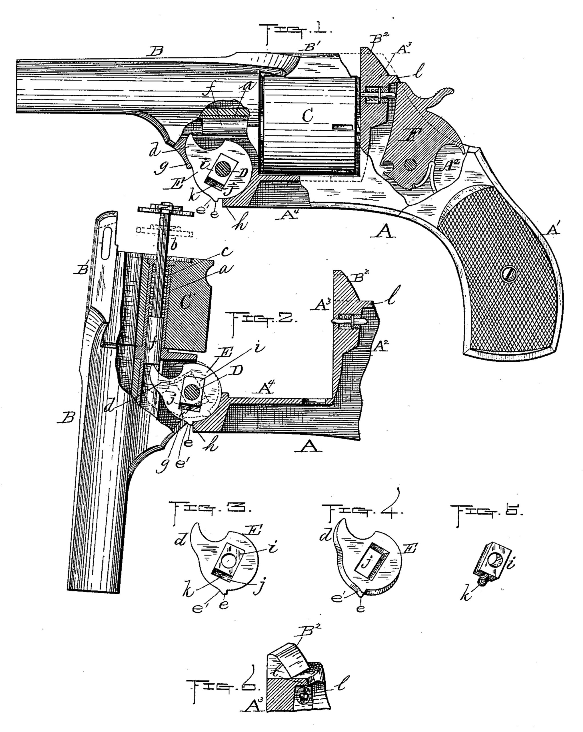
Figure 1 represents a side view, partly in section, of so much of a revolver asis necessary to illustrate our improvements thereon. Fig. 2 represents a part of the revolver illustrated in Fig.1, with the barrel unlocked and dropped down from the frame, to better show the operation of one part of our improvements; and Figs. 3 to 6, inclusive, represent different views of our said improvements, hereinafter more fully explained.
Our invention relates to breech-loading fire-arms having a revolving cartridge-cylinder and cartridge-extracting mechanism.
It relates more particularly to the extractor disk and its operation of said cartridge-extracting mechanism, and to means for protecting the interior of the fire-arm from dust or similar substance around the hammer thereof when at half-cock.
Said invention consists in improvements in the construction and means of operating the extractor-disk and its finger to extract the cartridge-shells, with a view to simplifying the construction shown in the United States Patent No. 339,301, granted to Johnson, Torkelson, and Fyrberg, for improvements in fire-arms, under date of April 6, 1886.
It also consists in forming a flange or hood projecting rearward from the breech, adapted to fit over the top and side edges of the upper forward part of the hammer when at half-cock, so as to leave no intervening space opening between said hammer and the breech when it is in the aforesaid position, and thus, by forming a close joint around said front side of the hammer, excluding all dust and similar particles from entering at this point and impairing the action of the working parts, it also serving to : lessen the liability to accidents by premature discharge in carrying the fire-arm.
To enable others skilled in the art to which our invention appertains to make and use the same, we will now proceed to describe it more in detail.
In the drawings, A represents the frame of the revolver, comprising the handle A’, the receiver A2, the breech or bridge A3, and the fore-hand A4. The barrel B is provided with the usual top strap, B’, extending back over the cylinder C, for connection with the top member, B2, of the breech, to which in practice it may be locked as ordinarily. It is pivoted to the frame by means of the bolt D, so that it may be swung down, as usual, when unlocked from the breech.
The cylinder C is fitted to rotate upon the usual sleeve, a, and said sleeve is provided with the usual extractor, b, and spring c.
The part marked E represents our improved extractor-disk, having the usual long projection or finger, d, and small projection or shoulder e, the former being adapted to bear upon the inner end of the extractor-spindle f against the pressure of spring c, and the latter to bear against a shoulder on the frame in extracting the empty cartridge-shells by the operation of dropping or swinging down the barrel B from the frame, as previously stated. The extractor disk E and its finger, when in their normal state or at rest, occupy the position shown in Fig. 1, with said finger free from the pressure of the extractor-spindle and its spring, with the front side of the finger resting against the inner side of the cam part g of barrel B and the shoulder e just in front of or in contact with the end h of the fore-hand.
The disk is arranged to yield to an outward pressure, so that it may be forced in ward, as and for the purpose hereinafter described, by arranging a square or rectangular-shaped plate, i, over the pivot-bolt D, which fits in a slot, j, formed in the disk, said slot being of sufficient length to admit of a lateral movement of the disk upon said plate and both parts rotating upon the pivot-bolt. Between plate i and the bottom of slot j, next to the shoulder e, is interposed a spiral or other spring, k, for producing a pressure of the plate against the pivot and thus forcing out the disk, so that said shoulder e will come against the end h of the fore-hand when said disk is forced or turned round on its pivot (after the extracting operation) by the extractor-spindle and spring, as hereinafter described.
The plate i, surrounding the pivot-bolt D, combined with the spring k and other parts, as pointed out in the claims, constitutes the main or essential feature of improvement in the extractor mechanism.
The method of obtaining a bearing of the shoulder e against the shoulder or projection h of the fore-hand is also an improvement over the method shown in the patent hereinbefore cited, which necessitates the forming of a “ pocket” under the part e’ of said fore-hand. The latter feature, however, is not new in itself, and we claim it only in combination with the first-mentioned improvement and other adjacent parts.
The operation may be briefly summed up as follows: Assuming that the various parts of the revolver are in their normal positions, ready for extracting the empty cartridge-shells after firing, and that the barrel has been unlocked from the frame, as usual, by now swinging or dropping down said barrel upon its pivot, the inner end of the extractor-spindle f is brought in contact with the end of the extractor-finger d of the disk, and, being held rigid by the shoulder e bearing against the fore-hand, as previously described, acts as a cam to force said spindle and the whole extractor back out of the sleeve in the cylinder, und thus extracting the empty cartridge-shells. As the barrel is continued to be moved down, the bearing or cam part g thereof comes in contact with the curved back e’ of the shoulder e and forces the extractor-disk in toward the cylinder, so that said shoulder e is carried beyond and disengaged from its holding-shoulder on the fore-hand. The disk, being released, is now (immediately upon its shoulder e passing by the shoulder h) sprung around by the ejector-spring from the position shown by full lines to that shown by dotted lines in Fig. 2, thereby allowing the ejector to be sprung forward into its normal position in the cylinder. The fire-arm is then reloaded by inserting new cartridges in the usual way, when the barrel is finally swung up into position and locked ready for firing. In the latter operation of swinging up the barrel the cam part g, coming in contact with the front side of the extractor-finger, rotates the disk so as to bring the shoulder e in front of the shoulder h, when said disk and its shoulder is sprung out by its spring into the position shown in Fig. 1, preparatory to again forcing out the extractor when the barrel is broken down, as hereinbefore described.
Our improvement for excluding the dust and similar substances from entering around the usual space in front of the hammer F when at half-cock consists in forming a flange or projection, l, on the breech or bridge of the fire-arm, which extends back and down therefrom over and at each side of the hammer-opening, just sufficient to lap over the top and side edges of the upper front part of said hammer, where it is usually exposed and unprotected. The use of said flange l is not only efficient for the above purpose, but also to prevent the arm from being prematurely discharged by the hammer becoming caught in the clothing or in other ways in carrying or handling said arm, said fange serving as an effectual guard against that portion of the hammer catching and being raised in any accidental manner, as will at once be seen. The length of said flange would of course be varied, as well as its shape, to conform to different makes of fire-arms.
We are aware that it is not new, in a broad sense, to overlap the upper end of the hammer of a fire-arm when at half-cock by its breech, the same being shown in the United States Patent No. 15,167, granted to F. Beals, dated June 24, 1856, for improvement in fire-arms; but in said patent the extreme upper end or terminal point of the hammer only is covered, leaving an open space under said end in front of the hammer, where the dust may freely enter, therefore not effecting the same result as by the use of our invention. We, however, in view of the above patent, limit our claim to the construction substantially as shown and described.
Having described our improvements, what we desire to secure by Letters Patent is–
1. In a breech-loading fire-arm, the combination of the main pivot D, shoulder h on the front end of the fore-hand A4, cam part g on the base of barrel B, and the extractor-spindle f, with the extractor-disk E, comprising a circular plate provided with a projection or finger, d, adapted to bear upon the inner end of the extractor-spindle in discharging the empty cartridge-shells; also provided with the shoulder e, adapted to bear against the shoulder h on the fore-hand when the barrel is swung down, and with a central opening or slot, j, at about right angles to finger d, whose length is about one-half the diameter of the circular plate, and which is a little wider than the diameter of pivot D, plate i, fitted in slot j laterally, and made shorter than said slot, so as to leave a space at the end next to shoulder e, and spring k, arranged in said space between the end of plate i and the bottom of slot j, substantially as shown and specified.
2. In a breech-loading fire-arm having a rebounding hammer adapted to assume a half cocked position after each discharge, the combination of said hammer and means for operating the same with the breech of said fire-arm, having a flange, l, projecting back and down therefrom over and at each side of the opening in the frame in which the hammer works, said flange overlapping the top and side edges of the upper front part of said hammer when at half-cock, so as to completely close the usual transverse opening or space between the outer line of the frame and front of the hammer, substantially as and for the purpose specified.
IVER, JOHNSON,
ANDREW EYRBERG.
Witness:
ALBERT A. BARKER,
WALTER B, NOURSE.