
US 391156
UNITED STATES PATENT OFFICE.
IVER JOHNSON AND ANDREW FYRBERG, OF WORCESTER, MASSACHUSETTS; SAID FYRBERG ASSIGNOR TO SAID JOHNSON.
REVOLVER.
SPECIFICATION forming part of Letters Patent No. 391,156, dated October 16, 1888. Application filed July 16, 1888. Serial No. 280,067. (No model.)
To all whom, it may concern:
Be it known that We, IVER JOHNSON and ANDREW FYRBERG, both of the city and county of Worcester, and State of Massachusetts, have invented certain new and useful Improvements in Revolvers; and we do hereby declare that the following is a full, clear, and exact description thereof, reference being had to the accompanying drawings, forming a part to of this specification, and in which–
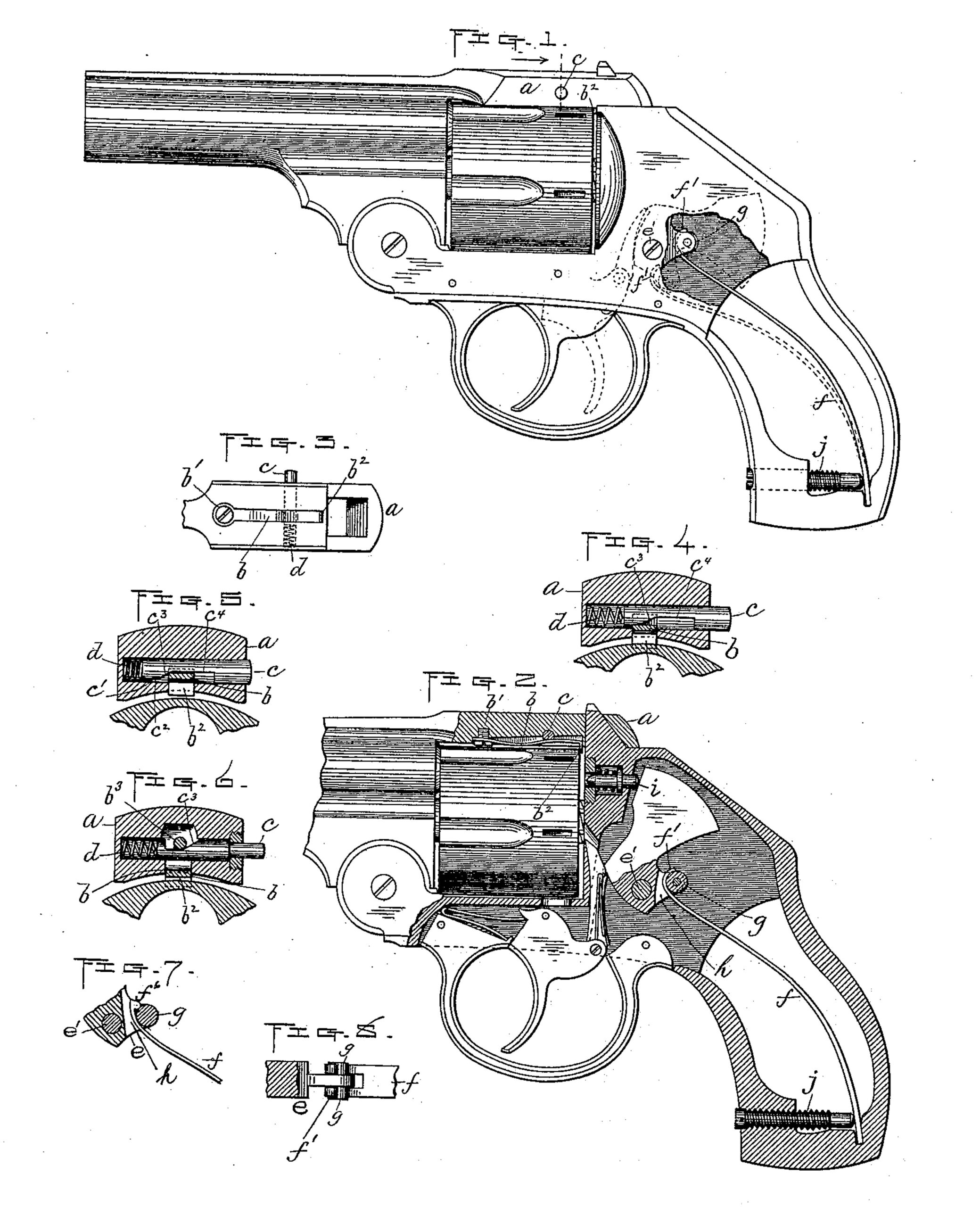
Figure 1 represents a side view of a revolver embodying our improvements, with one side of the handle removed and a part of the frame broken away to more fully illustrate the improvement upon the parts coming under the same. Fig. 2 is a part side view and part vertical section of so much of the revolver shown in Fig.1 as is necessary to illustrate our said improvements. Fig. 3 is a view of the under side of the barrel-strap, showing our improved cylinder-holding device, hereinafter more fully described. Figs. 4 and 5 represent, upon an enlarged scale, transverse sections through said barrel-strap and cylinder holding device, showing the operating parts of said device in different positions; and Figs. 6, 7, and 8 are modifications of our improvements, which will be hereinafter described.
Our invention consists of improvements in the cylinder-holding and hammer-rebounding mechanism of a revolver or other fire-arm. Following is a detailed description thereof with reference to the accompanying drawings.
The cylinder-holding device is arranged in the under side of the barrel-strap a and is constructed as follows: In a longitudinal slot or recess in said barrel-strap is fitted a flat spring, b, fastened at its forward end at b’ and having a downwardly-projecting hook or lip, b2, at its rear end, adapted to fit over the rear edge of the cylinder, as is best shown in Fig. 2. Between said spring b and the barrel-strap is arranged a spindle, c, fitted in a transverse opening in said strap, the purpose of which is to operate the spring to unlock the cylinder when it is desired to remove the same from the arm. The spindle is cut out upon its under side next to the spring to form the shoulder c’, the short level part c2, the bevel or cam c3, and longer level part, c4, and is forced outward longitudinally by the spiral spring d, fitted in the bottom of the opening in which the spindle is arranged and adapted to bear upon the inner end of said spindle, as is shown in Figs. 4 and 5.
The spindle is prevented from being forced out of its opening by its shoulder c’, bearing against the side of spring b. Said spring is in practice made so as to bear upward against the spindle, and said spindle, when in its normal position, is held by the spring d with its shoulder c’ against spring b, as aforesaid, and the short level part c2 against the top of said spring, as is shown in Fig. 2, thus holding the spring down in engagement with the cylinder, and consequently holding the latter in position longitudinally.
When it is desired to release the cylinder to withdraw it from the spindle upon which it turns, the spindle c is forced in by pressing upon its outer end, thereby causing the deepest portion of the recess in its under side to be brought in a vertical line with the spring b, which allows said spring to assume its natural elevated position, thus raising its hook out of engagement with the cylinder, when said cylinder may then be readily removed.
Various modifications in the foregoing construction may in practice be adopted to accomplish the same result by the use of a spring, b, and operating-spindle d, and we therefore do not limit ourselves to the exact construction shown and described. As an illustration, one other way is shown in Fig. 6. In adopting this construction the spring b is in practice made to bear down instead of up, as in the former instance, and it is provided with a loop, b3, on its upper side, through which the spin. dle passes, and said spindle is cut away upon the top instead of the bottom, with the bevel c3 reversed, so that when the spindle is forced in the spring will be drawn up to disengage its hook from the cylinder.
Our improvement in the hammer-rebounding mechanism consists in forming a projection, e, on the rear edge of the hammer back of its pivot e’, adapted to engage with the upper forward end of the hammer-spring f, where by the hammer may be sprung down to strike the firing-pin when released by the trigger mechanism, as usual, and also to cause said hammer to rebound and be held in a partially-raised position after each operation thereof. We accomplish the latter result by providing the aforesaid projection on the hammer with a roll, g, or its equivalent, a little above the level of the hammer-pivot when the parts occupy their normal positions, as is indicated by full lines in Figs. 1 and 2, and preferably arranged in a vertical slot, h, in said projection, and by forming a curved hook, f’, on the end of the hammer-spring f, adapted to fit over the front side of said roll, as is best shown in Fig. 2. Said end f’ is in practice curved sufficiently to produce a back-pressure at its extremity against the front of the roll when the hammer has been forced down to bring said roll above the level of the pivot. The upward pressure of the spring f is at this time nearly expended and the back draft on the hammer, being above its pivot, causes its upper end to be drawn back and held in said position, there by allowing the firing-pin i to spring back, so as not to retard the rotation of the cylinder when the construction shown in the drawings is adopted, or to be drawn back when formed or fastened upon the hammer.
The rebounding action of said hammer may be regulated to a greater or less degree by means of a screw, j, fitted to turn in a threaded longitudinal opening formed in the front side of the handle near its lower end, said screw being adapted to bear against the front side of the hammer-spring f. The back motion of the hammer is increased by turning the screw in and lessened by relieving the pressure on said spring.
In Fig. 7 we have shown a cross-connection formed integral with the hammer in lieu of the roll g, while in Fig. 8 studs are formed on each side of the hammer projection and the curved end f’ of spring f is made fork-shaped to fit over the same. The same result, it is obvious, is effected by either construction as by that first described, and we therefore do not limit ourselves thereto or to the particular shape of the curved end f’, the essential feature thereof being to obtain a bearing against the front of the roll to produce the aforesaid back-pressure.
What we claim, and desire to secure by Letters Patent, is–
1. In a revolver, the combination of the barrel strap having a longitudinal slot in its under side just forward of the usual catch-post opening, with a flat spring, b, fitted in said longitudinal slot and fastened therein at its forward end, also having a hook, b2, at its rear end adapted to fit over the edge of the rear end of the cylinder, an operating-spindle, c, fitted in a transverse opening in the barrel strap in front of the usual catch-bolt opening and having a cam, c3, adapted to engage with the free hook end of the spring b, also having a shoulder, c’, adapted to come and hold against said spring b to control the outward longitudinal movements of said spindle, and a spiral spring, d, fitted in the spindle – opening and adapted to bear against the inner end of said spindle, whereby the spring b may be operated independent of the usual catch-post bolt, substantially as and for the purpose set forth.
2. In a fire-arm, the combination of the hammer having a rear projection provided with a roll, hub, or its equivalent a little above the level of the hammer-pivot when the parts occupy their normal positions, with the hammer spring having its upper forward end curved or otherwise shaped to fit over the front side of said roll or its equivalent, whereby a back pressure is produced to impart a rebounding action to the hammer and to hold the same partially raised, substantially as shown and specified.
3. In a fire-arm, the combination of the hammer having a rear projection provided with a roll, hub, or its equivalent a little above the level of the hammer-pivot when the parts occupy their normal positions, with the hammer-spring having its upper forward end curved or otherwise shaped to produce a back-pressure against said roll or its equivalent, whereby a rebounding action is imparted to the hammer, and a screw fitted in the front side of the handle near its lower end adapted to bear against the front side of the hammer spring to regulate said rebounding action, substantially as shown and specified.
IVER JOHNSON,
ANDREW FYRBERG.
Witnesses:
A. A. BARKER,
LUCIUS. W. BRIGGS.