
US 391154
UNITED STATES PATENT OFFICE.
IVER JOHNSON AND ANDREW FYRBERG, OF WORCESTER, MASSACHUSETTS; SAID FYRBERG ASSIGNOR TO SAID JOHNSON.
REVOLVER.
SPECIFICATION forming part of Letters Patent No. 391,154, dated October 16, 1888, Application filed May 18, 1888. Serial No. 274,289.
To all, whom it may concern:
Be it known that we, IVER JOHNSON and ANDREW FYRBERG, both of the city and county of Worcester, and State of Massachusetts, have invented certain new and useful Improvements in Revolvers; and we do hereby declare that the following is a full, clear, and exact description thereof, reference being had to the accompanying drawings, forming a part of this specification, and in which–
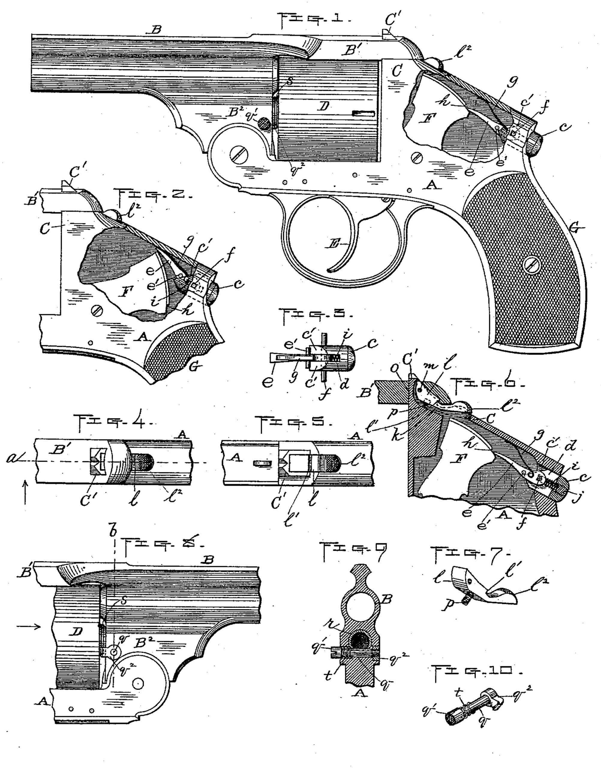
Figure 1 represents a side view of so much of a revolver as is necessary to illustrate our improvements, portions thereof being broken away to show said improvements more fully. Fig. 2 is a similar view to Fig. 1 of a part of the revolver, showing portions of our improvements in different positions from those shown in Fig. 1, as will be hereinafter more fully specified. Fig. 3 is a detached plan view of our improved hammer-locking device, also hereinafter described. Fig. 4 is a plan view of a portion of the barrel-strap and bridge of the revolver, also showing our improved lock device for locking said strap to the bridge. Fig. 5 is a similar view to Fig. 4 with the barrel-strap removed to show said locking device more fully. Fig. 6 is a central vertical section through the parts shown in Fig. 2, with the hammer and its locking device in the positions shown in Fig. 1, said section being taken at the point indicated by line a in Fig. 4. Fig. 7 is a detached perspective view of the aforesaid barrel-strap-locking device. Fig. 8 is a side view opposite from that shown in Fig. 1 of a part of the revolver, showing one end of our improved cylinder-locking device, hereinafter described. Fig. 9 is a vertical transverse section taken on line b, Fig. 8, looking in the direction of the arrow, same figure; and Fig. 10 is a detached perspective view of our aforesaid cylinder-locking device.
Our invention relates more particularly to revolvers, but is equally applicable to other styles and makes of fire-arms; and it consists in an improved hammer-locking device, an improved barrel-strap-locking device, and an improved device for locking the cylinder to the frame, as will be hereinafter more fully set forth.
To enable others skilled in the art to which our invention appertains to make and use the same, we will now proceed to describe it more in detail.
In the drawings, the parts marked A represents the frame, B the barrel, B’ the barrel-strap, C the bridge of the frame having the post C’ thereon, D the cylinder, E the trigger, and F the hammer, of the revolver.
Our improved hammer-locking device is constructed and arranged in the following manner: in the rear of the frame above the handle G and back of the hammer F is arranged, in a suitable longitudinal opening in said frame, a slide, c, which is provided with a vertical slot, d, to receive a spring-lever, e, and with a suitable transverse slot to receive a holding-pin, f, passed in this instance horizontally and transversely through the frame and said transverse slot in the slide c. The lever e is hinged at its rear end upon said pin f, and it has a constant downward pressure exerted thereon to force its forward end down upon the rear end of the hammer by means of a suitable spring, g, which in this instance is interposed between said lever and the under side of the upper part of frame A.
Upon the rear upper end of the hammer F is formed a notch or shoulder, h, which is adapted to strike and hold against the forward end of the lever e should said hammer be accidentally raised or forced back, thus preventing the premature discharge of the arm.
When it is desired to discharge said arm, the lever e is raised above the notch h, as shown in Fig. 2, prior to pulling upon the trigger to raise the hammer by pushing in the slide c, said operation causing the forward inclined or cam part c’ of said lever to pass under and against a transverse flange or pin, e’, in the lever e, thereby raising said lever above the notch, as aforesaid, and thus permitting the hammer to be operated. In this instance the slide is beveled at both sides of its vertical slot, and the transverse pin e’ projects from both sides of the lever, as is indicated in Fig. 3. Therefore the slide has a bearing at both sides of the lever in lifting its forward end above the notch in the hammer, as previously described. The slide is made to assume its normal position (shown in Figs, 1 and 6) after each operation thereof by means of a suitable spring, i, fitted in a longitudinal opening in the slide, and having a bearing at its inner end against the rear end of lever e and at its other end against the slide.
For the purpose of convenience in fitting the spring in position the opening in the slide is, in practice, preferably extended through to its rear end, and a screw, j, fitted in the end to hold said spring in position, as shown in Fig. 6.
In operating the revolver the handle is grasped in the hand with the forefinger over the trigger, as usual, thus bringing the hand, between the thumb and forefinger, against the outer end of the slide c. By now pressing against said slide to elevate lever e and then pulling the trigger said revolver may be discharged.
The locking device being located in the position shown and described, no more inconvenience is experienced in discharging the arm than in firing other revolvers not thus provided with a safety-lock, and, being located at a considerable distance from the trigger, the liability of accidental discharge is reduced to a minimum, it being quite improbable that both the slide c should be pushed in and the trigger pulled back accidentally in such a manner as to cause the premature discharge of said arm.
Our improved barrel strap-locking device is constructed and arranged as follows: In a central vertical slot, k, formed in the rear portion of the post C’ and upper part of the bridge C, (see Fig. 6,) is fitted a lever, l, hinged at its forward upper end to a pin, m, passed transversely through the upper end of said post and the lever. Upon the upper side of said lever is formed a notch or shoulder, l’, which, when the parts are locked, as indicated in said Fig. 6, engages with a corresponding internal notch or shoulder, n, formed on the rear end of the barrel-strap B near the bottom and rear end of the usual vertical slot, o, formed in said strap to receive the post C’. The lever is held in engagement with said notch in the strap by means of a suitable spring, p–in this instance arranged between the under side of the lever and the bottom of the slot in which said lever is fitted. The outer rear end, l2, of lever l is extended above the surface of the frame and sufficient space is provided for under said end to admit of the lever being depressed so as to disengage its notch from the notch in the strap when it is desired to unlock the parts to swing down the barrel in the usual way. To facilitate said operation of depressing the outer end of the lever for the aforesaid purpose, it is preferable in practice to mill or roughen the top surface of the rear end of the lever, as shown in the drawings.
A very simple and effective barrel-strap locking device is thus produced, as will at once be seen, which may be conveniently operated and is not liable to get out of repair.
We will now describe the cylinder-locking device shown in Figs. 8, 9, and 10 of the drawings. Said locking device, as well as that for locking the hammer previously described, constitutes improvements upon the devices for similar purposes shown and described in our United States Patent No. 379,225, dated March 13, 1888.
Our present improved cylinder-locking device consists of a spindle, q, fitted in a transverse opening formed in the barrel base B2 and passing through the under side of the cylinder-spindle r, (see Fig. 9,) thus serving to hold said spindle as well as to lock the cylinder, as hereinafter described. Said spindle q is provided at one end with a head, q’, whereby it may be operated, and with a flange or hook, of, at its opposite end, adapted to engage with the peripheral grooves, formed in the hub of the cylinder D, as shown in Fig. 8. The hook q2 is kept in engagement with the aforesaid groove s, except when forcibly pushed out therefrom, by means of a suitable spring, t–in this instance fitted over the spindle q in an enlarged opening or chamber in the barrel-base just back of the head q’ of the spindle, as is shown in Fig. 9–said spring bearing at one end against the head and at its opposite end against the barrel-base. The opening or chamber for the spring is made sufficiently large to permit the head q’ to be pushed therein to disengage the hook q2 from the groove in the cylinder-hub to unlock the cylinder.
In fitting the spindle q in position the hook q2 is removed from the end of the spindle and said spindle then inserted into its opening, after which the hook is fitted against the end of the spindle and said spindle then turned into the hook part, the hook end of the spindle being threaded and the hook part provided with a correspondingly-threaded opening for said purpose, as is indicated in Fig. 9.
To facilitate turning the spindle into the hook part, as aforesaid, the head thereof may be slotted transversely, as shown in Figs. 9 and 10, so as to be operated by a screw-driver. The hook part is preferably recessed flush with the face of the barrel-base when in its normal position, as shown in Fig. 9.
Although we prefer in practice to construct the various parts as hereinbefore described, and shown in the drawings, we do not limit ourselves thereto, but reserve the right to make such modifications therein as may be deemed advisable under different circumstances in carrying out the same results.
We are aware of the United States Patent No. 371,532, to D. B. Wesson, dated October 11, 1887, for improvement in revolvers, in which is shown a barrel-strap-locking device consisting of a lever or spring-actuated dog hinged in the strap-opening and engaging with the usual catch post, and another lever hinged in the frame back of said post, and make no claim to the construction therein set forth.
What we claim, and desire to secure by Letters Patent, is–
1. A hammer-locking device arranged in the upper back part of the frame above the handle and back of the hammer of the fire-arm, consisting of a slide piece fitted to work longitudinally in said frame, having means for guiding the same and for exerting a yielding back pressure thereon, also having its forward end beveled or cam-shaped, substantially as described, a lever arranged in front of said slide hinged to a stationary bearing at its rear end, and whose forward end is adapted to engage with a notch in the rear upper end of the hammer when the latter is forced back, also having one or more lateral projections or flanges against which the beveled end of the slide may bear to lift the forward end of said lever, and means for exerting a downward pressure to keep said forward end in engagement with the hammer-notch, except when forcibly elevated therefrom, substantially as shown and specified.
2. In a fire-arm, the combination of the slide c, fitted to work forward and back in a longitudinal opening formed in the upper back end of the frame, above the handle and back of the hammer, also having means for guiding the same, means for exerting a yielding back pressure thereon, and whose forward end is beveled or cam-shaped, substantially as described, with a lever, e, hinged at its rear end to a stationary bearing and whose forward end is adapted to engage with a notch on the upper rear end of the hammer, also having one or more lateral projections or flanges against which the beveled end of the slide c may bear to lift the forward end of the lever above the hammer-notch, the spring g, or its equivalent, for exerting a downward pressure upon the forward end of the lever, and hammer F, having the notch h, as aforesaid, substantially as and for the purpose set forth.
3. In a fire-arm, a barrel-strap-locking device consisting of a lever fitted in a vertical longitudinal slot formed in the back of the post and upper part of the bridge, and hinged at its forward upper end to a stationary bearing in the post, also having a notch in its upper side adapted to engage with a corresponding internal notch formed in the barrel-strap and having its rear end elevated a little above the frame, when in its normal position, so as to admit of said end being forced down to disengage and unlock the lever from the notch in the barrel-strap, means for exerting an upward pressure upon the lever back of its hinged point, and said barrel strap having an internal notch near the bottom and rear side of the usual vertical slot formed therein to receive the post and adapted to engage with the notch in the spring-lever, substantially as shown and specified.
4. In a fire-arm, the combination of the barrel-strap B’, having an internal notch near the bottom and rear side of the usual vertical slot formed in said barrel-strap to receive the post C’, and said post, and bridge C, having a vertical longitudinal slot therein, substantially as described, with a lever, l, fitted in said slot in the post and bridge and hinged at its forward upper end to a stationary bearing in the post, also having a notch, l’, in its upper side adapted to engage with the internal notch in the barrel-strap and whose rear end is elevated a little above the frame when in its normal position, so as to admit of said end being forced down to disengage and unlock the lever from the notch in the barrel-strap, and means for exerting an upward pressure upon the lever back of its hinged point, substantially as and for the purpose set forth.
5. In a fire-arm, the combination of the barrel-base B2, having a transverse opening therein at the lower back end thereof, substantially as described and shown, and the cylinder-hub having a peripheral groove, s, therein, with a spindle, q, fitted in said transverse opening, having the operating-head q’ at one end, the hook q2 at its opposite end, and means, substantially as described, for exerting a pressure upon the spindle in the direction of its head, substantially as and for the purpose set forth.
IVER JOHNSON,
ANDREW FYRBERG.
Witnesses:
A. A. BARKER,
W. B. NOURSE.