
US 379227
UNITED STATES PATENT OFFICE.
IVER JOHNSON AND ANDREW FYRBERG, OF WORCESTER, MASSACHUSETTS; SAID FYRBERG ASSIGNOR TO SAID JOHNSON.
REVOLVER.
SPECIFICATION forming part of Letters Patent No. 379,227, dated March 13, 1888. Application filed July 29, 1887. Serial No. 245,584. (No model.)
To all, whom it may concern:
Be it known that we, IVER JOHNSON and ANDREW FYRBERG, both of Worcester, in the County of Worcester and State of Massachusetts, have invented certain new and useful Improvements in Revolvers; and we do hereby declare that the following is a full, clear, and exact description of the same, reference being had to the accompanying drawings, forming a part of this specification, and in which–
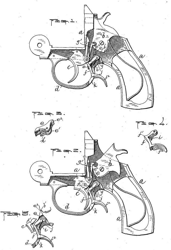
Figures l and 2 represent similar side views, partly in section, of so much of a revolver as is necessary to illustrate our aforesaid improvements thereon, with the operating parts shown in different positions, as hereinafter more fully described. Figs. 3 and 4 are perspective views of the parts embodying said improvements, and Fig. 5 is a modification of our invention hereinafter more fully described.
Our invention relates to the mechanism for locking the trigger of a revolver or other fire-arm, and more particularly to improvements in the lock mechanism shown and described in the United States Patent No. 345,974, granted to I. Johnson, R. T. Torkelson, and A. Fyrberg, for improvement in revolvers, dated July 20, 1886.
Our present improvement consists in combining with the trigger, sear, and hammer of a fire-arm a hinged lock-lever having means for forcing the same toward the trigger, and also means whereby it may be operated back of and outside of the trigger-guard, as hereinafter more fully set forth.
To enable others to obtain a full and clear understanding of our said invention, we will now proceed to describe it more in detail.
In the drawings, the parts marked a represent the frame of the revolver; b, the hammer; c, the trigger; d, the trigger-guard; e, the sear, and f our improved lock-lever, arranged within a central slot, e’, formed in said sear.
The sear and lock-lever are preferably hinged upon the same pivot-pin, g, as shown in Figs. 1 and 2, for the purpose of economy in the construction; but, if desired, only said sear may be hinged to said pivot and the lever hinged to the sear, as indicated in Fig. 5.
In addition to the usual purpose of the sear, it in this instance serves to guide and hold the lock-lever in position laterally. Both the sear and said lock-lever have a back-pressure exerted against the same by means of the springs h and i, respectively, said springs being in this instance interposed between said sear and lever and the part j of the trigger guard, the spring h exerting a power to force the end e2 of the sear toward the hammer, so as to catch in its notches b’, and the spring i to force the forward end f’ of the lock-lever toward the trigger, so as to catch and hold against a shoulder in the upper rear end thereof, as shown in Fig. 1, when the trigger is pulled back. Said Fig. 1 represents the arm with the hammer down and the trigger locked against the lever f. When unlocked, as hereinafter described, said lever has a bearing against the back curved side of the trigger, as shown in Fig. 2. It is formed so as to extend down and back from its end f through a slot, k, in the trigger-guard, and terminates in a curved end, f2, similar to that of the trigger, by means of which it may be drawn back to unlock said trigger.
In unlocking and discharging the revolver it is grasped in the hand in the usual way, except that, in addition to placing the fore or index finger over the trigger, the middle finger is also placed over the curved end f2 of the lock lever f. Being thus held, the first operation is to unlock the trigger by pulling back upon said lever f, and immediately following said operation the trigger is pulled back, thus forcing up the raiser g’ to operate the hammer and discharge the arm in the usual way. In this instance we have shown our improvement applied to what is commonly known as a “self cocking’ revolver having an exposed hammer; but we do not limit ourselves thereto, the same being applicable to other forms and styles of fire-arms.
In practice the lever f is preferably arranged in a central slot in the sear, as hereinbefore described; but, if desired, it may be placed in a recess formed in the side of said sear, (see Fig. 5,) without departing from the principle of our invention.
The advantage we claim of this invention over the one previously cited is that, the trigger and lock-lever being operated independent of each other, the arm is less liable to be prematurely discharged, and in consequence decreasing the liability to injury by accidents.
Having thus fully described our said invention, what we claim as new, and desire to secure by Letters Patent, is–
In a fire-arm, the combination of the trigger, sear, and hammer with a lock-lever hinged at its upper end and fitted to work in a longitudinal slot or recess in the sear, and having a projection upon its front side near its upper end adapted to engage with a shoulder or notch on the back side of the trigger, also having a projection extending down and back of the trigger guard, preferably through a longitudinal slot in said trigger-guard, and provided with a suitable spring for exerting a forward pressure thereon, substantially as and for the purpose set forth.
IVER JOHNSON,
ANDREW FYRBERG.
Witnesses:
ALBERT A. BARKER,
WALTER B. NOURSE.