
US 379226
UNITED STATES PATENT OFFICE.
IVER JOHNSON AND ANDREW FYRBERG,OF WORCESTER,MASSACHUSETTS;
SAID FYRBERG ASSIGNOR TO SAID JOHNSON.
REVOLVER.
SPECIFICATION forming part of Letters Patent No. 379,226, dated March 13,1888.
Application filed July 29,1887. Serial No. 84558. (No model.)
To all whom it may concern:
Be it known that we, IVER JOHNSON and ANDREW FYRBERG, of Worcester, in the County of Worcester and State of Massachusetts, have invented certain new and useful Improvements in Revolvers; and we do hereby declare that the following is a full, clear, and exact description of the same, reference being had to the accompanying drawings, forming a part of this specification, and in which–
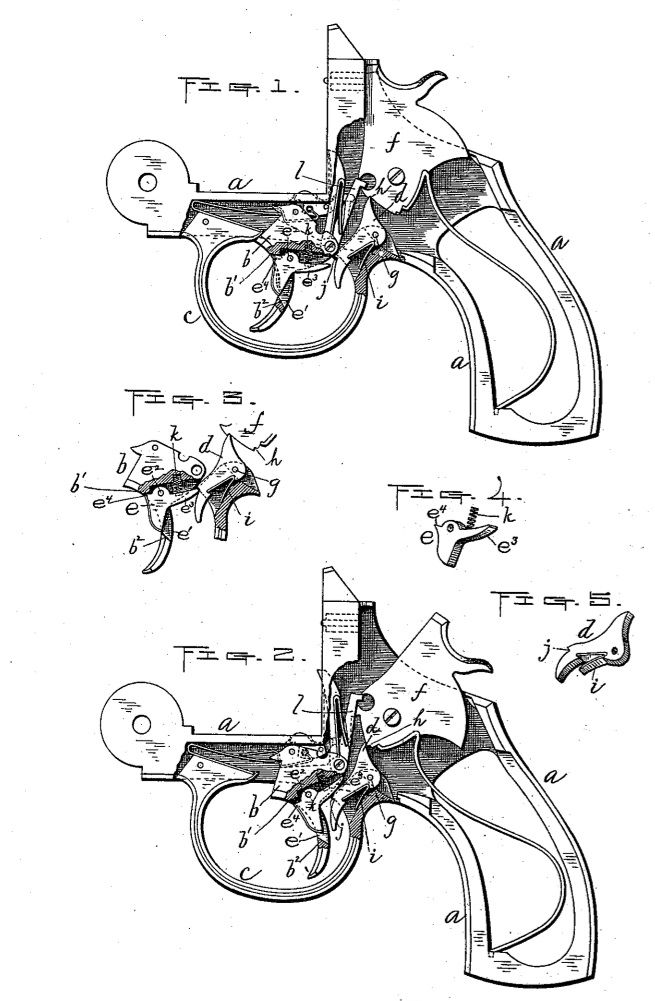
Figures l and 2 represent similar side views, partly in section, of so much of a revolver as is necessary to illustrate our aforesaid improvements thereon,with the operating parts shown in different positions, as hereinafter more fully set forth. Fig.3 represents said improvements in still other positions, and Figs.4 and 5 are perspective views of parts relating thereto.
Our invention relates to the mechanism for locking the trigger of a revolver or other fire-arm; and it consists in combining with the trigger, sear, and hammer of a fire-arm a locking-lever hinged to the trigger, having means for forcing its rear end outward, and adapted to hold against a notch in said sear when thus sprung out, as hereinafter more fully set forth.
To enable those skilled in the art to which our invention appertains to make and use the same, we will now proceed to describe it more in detail.
In the drawings, a represents the frame, b the trigger, c the trigger-guard, d the sear, e the lock-lever, and f the hammer, of our improved revolver.
The hammer and trigger are both hinged and operated in the usual way. The sear is in this instance hinged upon the back holding pin, g, of the trigger-guard, and its lower end forced forward, so as to engage its upper end with the usual notches, h, on the hammer, by means of the spring i, interposed between its backside and said trigger-guard. Said sear is also provided upon its front side with a notch, j, for the purpose hereinafter specified. The lock-lever e is in this instance arranged in a central slot, e’, formed in the trigger, and is hinged at its upper end on a pin, e2, passed transversely through said trigger. If preferred, however, it may be arranged in a recess formed in the side of the trigger, as indicated in Fig.3. Said lock-lever is made of the proper form to project a little in front of the trigger when in its normal position, (shown in Figs.1 and 3) and with a rear projection, e3, adapted to engage with the notch j on the sear when the trigger is drawn back, as indicated in Fig,3, thereby locking said trigger and preventing the arm from being accidentally discharged. An outward pressure is exerted against the projection e3, so that it will thus engage with the notch j by means of a spring, k, interposed between said projection and the trigger. The backward movement of the lock-lever may be controlled by the upper front portion, e4, thereof coming against the part b’ of the trigger, or its lower end striking against the shoulder b2 at the bottom of the slot or recess in said trigger.
By thus constructing the aforesaid lock mechanism it will at once be seen that should the trigger be accidentally pulled back by catching in the clothing or otherwise, the arm cannot be prematurely discharged unless the lock-lever is also pulled back with it, while at the same time said arm may be readily discharged, when desired, by drawing upon the trigger with the finger in the usual way care being of course taken to adjust said finger over the front part of the 1ock-lever, that the latter will be forced back in advance of the trigger and prevented from engaging with the notch on the sear, as indicated by dotted lines in Fig.1.
In said Fig.1 the various operating parts are shown in their normal positions, ready for firing, and in Fig.2 in the various positions which they occupy after unlocking and drawing back the trigger, just prior to the release of the hammer, by the raiser l, to discharge the arm, while in Fig.3 the trigger is shown drawn back without operating the lock-lever, to illustrate the manner of locking said trigger, as previously described.
In this instance we have shown our improvement applied to what is commonly known as a “self-cocking” revolver having an exposed hammer; but we do not limit ourselves there to, the same being applicable to other forms and styles of fire-arms.
From the foregoing description it will be observed that a simple and effective lock device is produced, which at the same time is strong and durable, and not liable to get out of repair.
By the application thereof to practice the danger by accidental or premature discharge is greatly reduced over fire-arms not provided with such safeguard.
We are aware that it is not new to hinge a lever to the trigger of a fire-arm, the same being shown in the United States Patent No.346,327, to J. T. Smith, dated July 26,1886; but said 1everis employed to produce a different result from that employed in our improved revolver–viz., to prevent the engagement of the sear with the hammer, whereas in our revolver said lever serves, through the sear, to lock the hammer, as and for the purpose previously described. In view of the above patent we make no claim, broadly, to a lever hinged to the trigger.
What we claim as our invention, and desire to secure by Letters Patent, is–
The combination of the hammer f and sear d, arranged to operate substantially as described, said sear provided with a shoulder or notch, j, upon the front side thereof, near its lower end, with the lock-lever e, hinged at its upper end to the trigger b in a slot or recess, e’, formed therein, said lock-lever being made to project a little in front of the trigger-finger when in its normal position, and also provided with a projection, e3, extending back and up therefrom, and adapted to engage with the aforesaid shoulder or notch j on the sear when the trigger is pulled back, the spring k interposed between said projection e3 and the trigger, and said trigger, all constructed and arranged to operate substantially as and for the purpose set forth.
IVER JOHNSON,
ANDREW FYRBERG.
Witnesses:
ALBERT A. BARKER,
WALTER B. NOURSE.