
US 379225
UNITED STATES PATENT OFFICE.
IVER JOHNSON AND ANDREW FYRBERG, OF WORCESTER, MASSACHUSETTS; SAID FYRBERG ASSIGNOR TO SAID JOHNSON.
BARREL LOCK FOR REVOLVERS.
SPECIFICATION forming part of Letters Patent No. 379,225, dated March 13, 1888. Application filed November 3, 1887. Serial No. 254,189. (No model.)
To all whom it may concern:
Be it known that we, IVER JOHNSON and ANDREW FYRBERG, both of Worcester, in the County of Worcester and State of Massachusetts, have invented certain new and useful Improvements in Fire-Arms; and we do hereby declare that the following is a full, clear, and exact description of the same, reference being had to the accompanying drawings, forming a part of this specification, and in which–
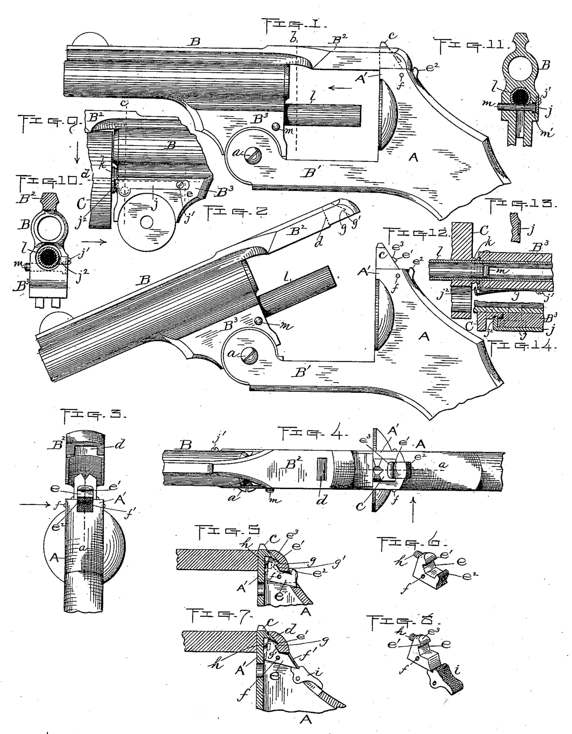
Figure 1 represents so much of a revolver as is necessary to illustrate our aforesaid improvements, with the barrel in its normal position and locked. Fig. 2 is a similar side view of the parts shown in Fig. 1, with the barrel unlocked and swung down. Figs. 3 and 4 are a rear end view and plan view, respectively, of the aforesaid parts in the positions shown in Fig. 2. Fig. 5 is a vertical longitudinal section through the parts to which our improvements relate, taken at the point indicated by lines a, Figs. 3 and 4. Fig. 6 is a detail perspective view of our improved spring lock lever or dog, hereinafter more fully described. Figs. 7 and 8 are similar views to Figs. 5 and 6, showing modifications in the construction, also hereinafter described. Fig. 9 is an opposite side view from Figs. 1 and 2 of so much of a revolver as is necessary to illustrate our improved cylinder and sleeve-locking device. Fig. 10 is a transverse section taken on line b, Fig. 1, looking in the direction of the arrow, same figure. Fig. 11 is also a transverse section taken on line c, Fig. 9, looking toward the right, as indicated by the arrow. Fig. 12 is a horizontal section on line d, Fig. 9, looking down, as is also shown by arrow. Fig. 13 is a transverse vertical section taken on line e, Fig. 9, showing one way of fastening the cylinder lock-spring, hereinafter described; and Fig. 14 represents an enlarged sectional detail of a part of our improvements, also hereinafter described.
Our invention relates to breech-loading fire-arms having a hinged barrel, and more particularly to improvements in the devices for locking and unlocking said barrel to and from the bridge of said fire-arms; also, for locking and unlocking the cylinder and its sleeve to and from the barrel, as hereinafter set forth.
Following is a detailed description of our improvements, with reference to the accompanying drawings.
The part marked A represents the frame, and B the barrel, which is hinged at b to the fore-hand B’ of said frame, and provided with the back-strap B2, by means of which connection is made with the bridge A’ to lock and unlock said barrel, as will now be described.
Upon the bridge A’ is formed the usual up right flange or post, c, which is adapted to enter the vertical opening d in the rear end of strap B2, as ordinarily, when the barrel and strap are swung into their normal positions, as shown in Fig. 1. The strap is locked to said post by means of a dog, e, hinged at f in a vertical longitudinal slot, f’, formed in said post and bridge A’, and having a lip, e’, upon the back side of its upper end, adapted to engage with and hold against a horizontal shoulder, g, formed in the strap at the rear side of the vertical opening d, as shown in Figs. 2, 5, and 7.
A constant pressure is exerted upon the upper forward end of the dog e, to keep it in contact with the notched portion of the barrel-strap, by means of a suitable spring, h, interposed between the post c and said upper forward end of the dog. It is forced back against said pressure to unlock the strap by pressing forward and upward against an upwardly-turned flange, e2, formed on its outer end, said force being most conveniently applied by placing the end of the thumb against the outer side of said flange e2 and pressing upon the same, as above stated. To facilitate the latter operation, the face of the flange e2 may be milled or roughened, as indicated in the drawings. When out of engagement with the notch or shoulder on the strap, the dog is prevented from being forced beyond its proper position by its spring by being made so that some portion thereof will strike and hold against either the post c or bridge A’.
In locking the barrel it is simply necessary to swing up the same with sufficient force to cause the strap to press back and slip down over the upper end of the dog, so that the lip e’ on said dog may be forced by its spring back of and in engagement with the shoulder g on said strap, as shown in Figs. 1, 5, and 7. Said operation is facilitated by beveling or curving the strap downward and backward below said shoulder g, as shown at g’, and the dog forward and upward above its lip e’, as shown at e3.
In Figs. 7 and 8 we have shown a lever, i, hinged just below the dog e, whereby said dog may be operated to unlock the barrel-strap by a downward instead of a forward and upward pressure, as previously described, the inner end of said lever being adapted to press up ward upon the outer end of the dog when its outer end is forced down by pressing the thumb upon the same. The latter construction, it will be observed, consists simply in leaving off the operating-flange e2 from the outer end of dog e and substituting therefor the separate hinged part or lever i, as above described. Otherwise the construction is the same as that relating to the first six figures of the drawings.
In view of the fact that no new elements are introduced, we claim the right to use either construction, as occasion requires.
Our improvements in the cylinder and sleeve locking mechanism consist of the following construction and arrangement of parts: A flat spring, j, is fitted horizontally in a correspondingly-shaped recess formed in one side of the base B3 of barrel B, flush with the surface thereof, and is fastened at its forward end by means of a screw, j’, by dovetailing the same into the barrel-base, as shown in Fig. 13, or in any other suitable and convenient manner. The end of said spring next to the cylinder C is bent inward at right angles to form the flange j2, which is adapted to engage with a peripheral groove formed in the hub k of said cylinder when the latter is fitted in position, as shown in Fig. 9, thereby holding the cylinder longitudinally and at the same time admitting of its turning freely on the usual sleeve, l. The cylinder is unlocked from the flange or catch j2 on spring j by forcing the catch end of said spring j outward, so as to disengage it from the groove in hub k, as shown in Fig. 12. This is done by pressing upon the outer end of a pin, m, fitted to slide transversely in the barrel-base. Said pin may be fastened at its inner end to the spring j or not, as desired. In this instance we have shown it separate therefrom, and held from being forced out of its opening by the spring by forming a head, m’, upon its inner end, countersunk into the barrel-base, as is best shown in Fig. 11. The operation of locking said parts is performed by simply slipping the cylinder over its sleeve and pressing the hub thereof against the flange j2, which causes the latter to spring out and engage with the peripheral groove in said hub. To facilitate said operation the ends of the hub and flange are rounded or beveled, as best shown by the enlarged section, Fig. 14. The pin m may serve not only the purpose previously described, but also to hold the sleeve l both longitudinally and from turning by making the parts so that said pin may pass through a transverse slot or opening in said sleeve, as shown in Figs. 11 and 12.
We reserve the right to combine the sleeve with the transverse sliding pin or not, as desired, said sleeve being inessential to the construction of the cylinder-locking device previously described.
We are aware that various devices have heretofore been patented for locking the barrel-strap to the bridge and the cylinder and its sleeve to the barrel, and therefore limit our invention to the specific construction herein set forth for accomplishing said results.
What we claim as new, and desire to secure by Letters Patent, is–
1. A barrel-lock mechanism for fire-arms, comprising, in combination, the barrel-strap B2, having the usual vertical opening, d, at its rear end and the horizontal shoulder g back of said vertical opening, the spring-dog e, hinged in a vertical longitudinal slot in the back of bridge A’, having the lip e’ upon the outer side of its upper end, adapted to engage with said shoulder g, also having means, substantially as described, whereby its upper end may be forced forward to disengage its lip from the shoulder g, and the said bridge A’, having the post c, substantially as set forth.
2. The combination of the barrel-strap B2, having the vertical opening d at its rear end and the horizontal shoulder or notch g back of said vertical opening, with the dog e, hinged in the longitudinal vertical slot f’, formed in the bridge A’ and its post c, and having the lip e’ upon the outer side of its upper end, also having means, substantially as described, whereby the same may be operated at its lower end to force forward its upper end to disengage its lip from the shoulder g, spring h, interposed between said upper end of the dog and post c, and bridge A’, having said post c, substantially as and for the purpose set forth.
3. In a fire-arm, the combination of the spring j, fitted in a horizontal recess in one side of the barrel-base B3, fastened at its forward end and having the inwardly-turned flange j2 at its opposite end, with the cylinder hub k, having a peripheral groove therein, and the operating-pin m, fitted to slide transversely in said barrel-base, also adapted to engage with the free end of spring j, substantially as and for the purpose set forth.
4. In a fire-arm, the combination of the spring j, fitted in a horizontal recess in one side of the barrel-base B3, fastened at its forward end and having the inwardly-turned flange j2 at its opposite end, with the cylinder hub k, having a peripheral groove therein, operating-pin m, fitted to slide transversely in said barrel-base, also adapted to engage with the free end of spring j, and sleeve l, having a transverse slot or groove to receive said pin m, substantially as and for the purposes set forth.
IVER JOHNSON,
ANDREW FYRBERG.
Witnesses:
WALTER B. NOURSE,
LUCIUS. W. BRIGGS.