
US 143855
UNITED STATES PATENT OFFICE.
WILLIAM S. SMOOT, OF ILION, NEW YORK, ASSIGNOR OF ONE-HALF HIS RIGHT TO E. REMINGTON & SONS, OF SAME PLACE.
IMPROVEMENT IN REVOLVING FIRE-ARMS.
Specification forming part of Letters Patent No. 143,855, dated October 21, 1873; application filed August 2, 1873.
To all whom it may concern:
Be it known that I, WILLIAM. S. SMOOT, of Ilion, in the county of Herkimer and State of New York, have invented certain Improvements in Revolvers, of which the following is a specification:
My invention relates to that class of fire-arms known as revolvers; and the invention consists in a peculiar manner of forming the barrel and frame of a single piece of metal in connection with the guard-strap; in a revolving recoil-shield of novel construction; a novel construction and arrangement of the ejector and center-pin, together with various other details of construction.
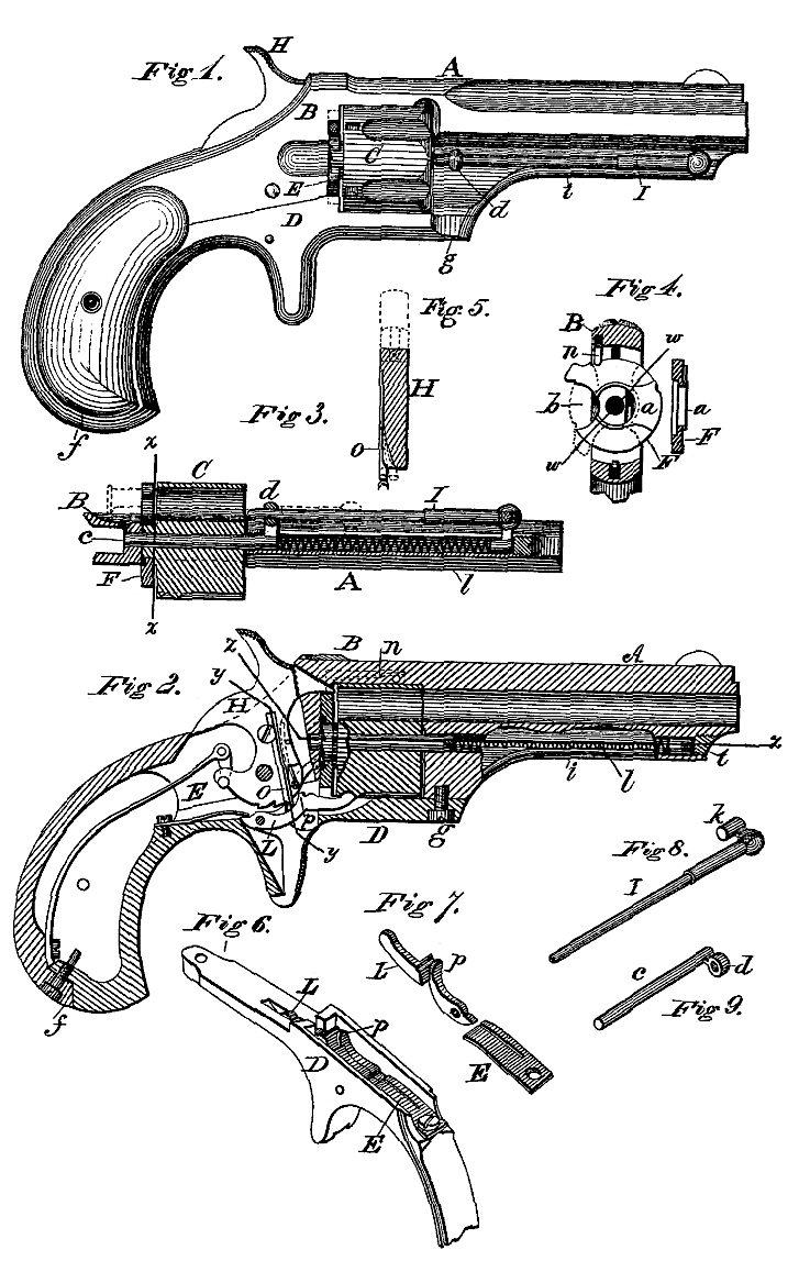
Figure 1 is a side elevation of the arm complete. Fig. 2 is a longitudinal section; Fig. 3, a longitudinal section on the line z z of Fig. 2; Fig. 4, a transverse section on the line x x of Fig. 3; Fig. 5, a transverse section of the hammer on the line y y of Fig. 2; Fig. 6, a view of the guard-strap detached, with its rear end broken away; Fig. 7, a perspective view of the stop and trigger-spring; Fig. 8, a perspective view of the ejector-rod detached, and Fig. 9 a perspective view of the center-pin detached.
In constructing my revolver, I make the barrel A and the frame B, with the bridge or strap that connects them above the cylinder C, all in one piece of metal, the rear end of the part B extending back far enough to form the upper portion of the handle, the guard-strap D, made also of a single piece, forming the lower portion of the handle and frame, the two parts being united by a screw, f, at the rear end, and by a screw, g, at the front, as shown clearly in Fig. 2, the hammer being pivoted in the part B, and the trigger and stop, with their springs F, being secured in the lower part or guard strap D, this mode of construction affording great convenience of manufacture, and also affording convenient access to the lock. The cylinder is constructed and mounted to revolve in the usual manner within the frame, and is held in place by a center-pin, c, shown in place in Fig. 3 and detached in Fig. 9. This pin c is inserted through a tube, i, which is bored out of the solid metal under the barrel, and parallel there with, as shown in Fig. 2, the pin c having projecting laterally from its front end a lug, d, which has a hole through it, as shown in Fig. 9, and which projects outward through a slot cut in the side of the tube i, as shown in Fig. 3. The ejector consists of a rod, I, which also has a lateral projection, as shown in Fig. 8, and which terminates in a cylindrical body, k, of such a size as to slide freely in the tube i, as shown in Fig. 3. This rod I is reduced in size for about two-thirds of its length, so that its smaller end will slide freely through the hole in the projection d on the center-pin, which thus forms a support and guide for the rear end of the rod, its front end being supported by the part k in the tube i. After the center-pin is inserted, I then place a spiral spring, l, in the tube i; then insert the rod I, with its projection or follower k bearing on the opposite end of the spring, which latter thus serves the double purpose of holding the center-pin in place, and also to force back the ejector-rod I after it has been shoved through a chamber of the cylinder to eject a shell or cartridge, the rod lying alongside of the tube i underneath the barrel, and in line with the chamber of the cylinder on that side. After the pin c, spring l, and rod I are inserted in their places, a plug, t, Fig. 2, is screwed into the outer or front end of the tube i, which secures them all in place.
The recoil-shield, instead of being formed solid on the frame, in the usual manner, consists of a separate circular plate, F, (shown in elevation, and in section in Fig. 4) and has a hole through its center, by which it is mounted on a hub projecting from the rear end of the cylinder C, as shown in Fig. 3, the plate F being cut away at one edge, as shown at b, Fig. 4, to permit the cartridge to be inserted through it into the cylinder. This plate F is provided on its edge with two notches, (shown in Fig. 4.) in which a spring, n, inserted in a recess in the frame above the cylinder, engages, and which serves to lock the recoil shield or plate F in place, and hold it open for the insertion of the cartridges, or hold it so as to close the opening when turned down, a small projection on the edge of the plate F, above the recess b, serving as a means of turning it in either direction. This recoil shield is provided on its front face with a projection, a, which extends all around the hole at its center, and which is also enlarged at one side, so as to extend out to the outer edge, and which enlarged portion is arranged to come directly behind the cartridge that is to be fired, when the recoil-shield is turned so as to close the opening through which the cartridges are inserted. The effect of this projection around the center is to prevent the cylinder from rotating in case a cartridge having too thick a head is inserted, thus giving notice at once; whereas the cylinder might otherwise be rotated until the thick-headed cartridge came in contact with the enlarged projection, when it could go no farther, in which case it would be far more difficult to remove it. The stop L, which locks the cylinder, is shown detached in Fig. 7, and in place in the guard-strap D in Figs. 2 and 6. Its rear portion is curved, and this curved portion terminates at its front in a rounded shoulder, p. This stop is made to engage with the cylinder by the pressure on its rear end of one arm of the spring E, the other arm of the spring resting on and operating the trigger. The stop is released by a spring, o, secured in a recess in the side of the hammer h, as shown in Fig. 2, this spring o being arranged to yield sidewise, as represented by the dotted lines in Fig. 5. As the hammer is drawn back, the lower end of this piece o presses upon the curved face of the stop L, thereby depressing its front end, and unlocking the cylinder. As soon as the cylinder has commenced to move, the end of o rides up over the shoulder p of the stop L, and then springs sidewise over the rounded end of the shoulder p, permitting the stop to rise again to engage with the cylinder, the forward motion of the hammer bringing the lower end of spring o back over the curved portion of the stop, so as to be in position to depress the stop again as the hammer is drawn back to recock the arm.
By this method of constructing and arranging the several parts, I am enabled to make a very compact and perfect revolver, and that operates in a most satisfactory manner.
Having described my invention, I claim–
1. As an improvement in revolvers, the barrel, bridge-strap, lock-frame, and upper portion of the handle made of a single piece, in combination with the guard-strap, united thereto by a longitudinal joint, substantially as described.
2. The center-pin C, held in place by the spring l of the ejector-rod I, substantially as described.
3. The center-pin C, provided with the projecting guide or eye d, in combination with the sliding ejector I, the said parts being constructed and arranged to operate as set forth.
4. The recoil-shield F, provided with an opening, b, in its edge, and arranged to turn in rear of the cylinder far enough to open or close the passage through which the cartridges are inserted or removed, substantially as described.
5. The rotating shield F, having on its face a projection, a, which extends in a reduced or narrow strip around the central hub on which the shield turns, substantially as and for the purpose set forth.
6. The shield F, in combination with the spring in, arranged to hold the shield in position when opened or closed, as set forth.
7. The stop L, provided with the rounded shoulder or projection p, in combination with the spring o located upon the hammer, said parts being constructed and arranged to operate substantially as described.
W. S. SMOOT.
Witnesses:
THOS. RICHARDSON,
W. C. DODGE.