
US 345974
UNITED STATES PATENT OFFICE.
IVER JOHNSON, REINHARD T. TORKELSON, AND ANDREW FYRBERG, OF WORCESTER, MASSACHUSETTS; SAID TORKELSON AND FYRBERG ASSIGNORS TO SAID JOHNSON
REVOLVER.
SPECIFICATION forming part of the Letters Patent No. 345,974, dated July 20, 1886.
Application filed March 27, 1886. Serial No. 196,787. (No model.)
To all whom it may concern:
Be it known that we, IVER JOHNSON, REINHARD T. TORKELSON, and ANDREW FYRBERG, all of Worcester, in the county of Worcester and State of Massachusetts, have invented certain new and useful Improvements to Fire-Arms; and we do hereby declare that the following is a full, clear, and exact description of the same, reference being had to the accompanying drawings, forming a part of the specification, and in which–
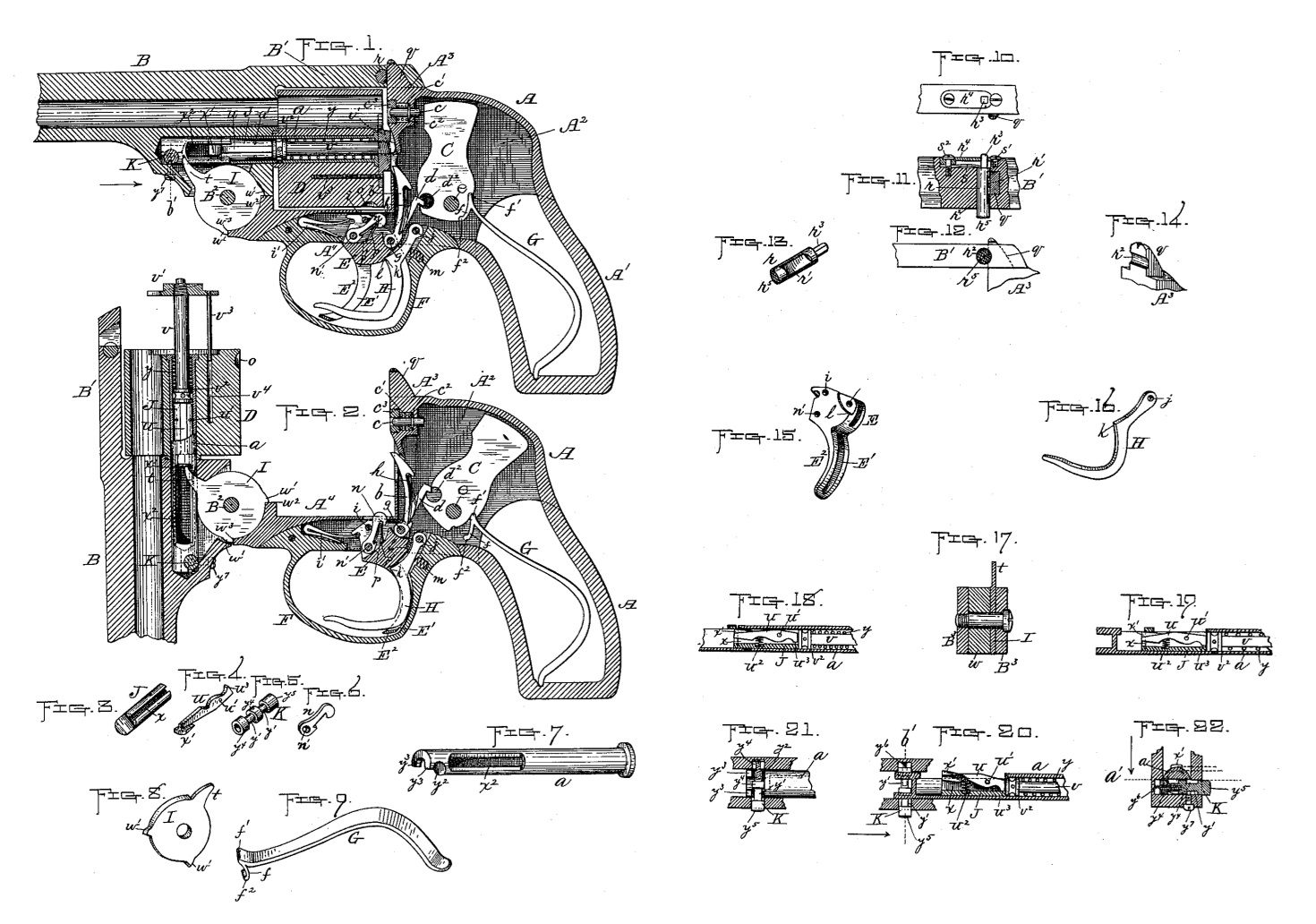
Figure 1 represents a central longitudinal section through so much of a fire-arm as is necessary to illustrate our improvements thereon, some of the parts being shown in elevation to more clearly illustrate their construction and operation, hereinafter more fully described. Fig. 2 represents a similar view to that shown in Fig. 1 of our improved fire-arm, with the barrel and parts attached thereto swung over and down to eject the cartridge-shells after firing preparatory to reloading said fire-arm in the usual way, said adjusted position also serving to more fully illustrate our improvements, as well as the construction and operation thereof. All the following figures represent details views of the various parts of our said improvements. Figs. 3, 4, 7, 8, 17, 18, and 19 are views of parts relating to the cartridge-shell-ejecting mechanism, different views thereof also being shown in Figs. 20 and 22 in connection with our improved cylinder-retaining pin. Figs. 5 and 21 also represent, in addition to Figs. 20 and 22, different views of said cylinder-retaining pin and its application to the fire-arm. Fig. 6 represents our improved cylinder-stop. Fig. 9 shows our improved mainspring for causing the hammer to rebound into its normal or half-cocked position after each discharge of the fire-arm. Figs. 10, 11, 12, 13, and 14 are different views of parts relating to the mechanism for locking the barrel of said fire-arm in its normal position; and Figs. 15 and 16 are views of the trigger and its locking-lever hereinafter more fully described.
Our invention relates to what are commonly known as “breech-loading fire-arms,” having a hinged barrel, a revolving cylinder, and an automatic cartridge-ejector, and comprises improvement in the means employed for causing the hammer to spring back or rebound into it normal half-cocked position after each partial rotation thereof in the operation of firing the arm; for locking and holding the barrel in its normal position; for operating the cartridge-shell ejector, and for locking and retaining the cylinder and parts connected therewith in position longitudinally, also the sleeve of said cylinder against a rotary movement, all of which improvements will be hereinafter more fully set forth.
To enable others skilled in the art to which our invention appertains to make and use the same, we will now proceed to describe it more in detail.
In the present instance we have shown our aforesaid improvements applied to an ordinary pocket-revolver; but we do not limit our invention thereto, as it is applicable to other forms of fire-arms whose operating parts are similar in construction and arrangement to the fire-arm hereinafter described, and shown in the drawings.
Referring to said drawings, the parts marked A represent the frame of the revolver, which comprises the handle A’, the receiver A2, the bridge A3, and forehand A4. B is the barrel, having the usual strap B’, at the rear end thereof. The part marked C is the hammer, D the cylinder, E the trigger, and F the trigger-guard, all of which parts are of ordinary well-known construction, and therefore require no further description, except in combination with our present improvements hereinafter described.
The cylinder D is fitter to turn on the sleeve a, which is held in the barrel, as hereinafter described, and said cylinder is operated, as usual, by means of the trigger E and a lever, b, hinged at its lower end to said trigger, the upper end of said lever being adapted to engage with the usual notches for turning the cylinder when the trigger is pulled back to force up its rotating lever aforesaid.
The operation of the hammer C in striking the firing-pin c to explode the cartridge, with the exception of the means employed for causing the rebound thereof into its normal half cocked position, (shown in Fig.1) is substantially like other revolvers of its class now in public use, said hammer being raised or sprung back, as shown in Fig. 2, preparatory to striking the firing-pin, by the operation of the trigger, and a lever, d, hinged thereto, whose upper end works in a transverse slot, d2, in the lower front edge of the hammer. In said operation of raising the hammer, when the upper end or head of lever d passes out of the slot d2 aforesaid, the mainspring G, which bears against said hammer above its pivot when thus sprung back, forces it forward to strike the firing-pin and explode the cartridge in the usual way.
The hammer is caused to rebound or spring back into its normal half-cocked position (shown in Fig. 1) after striking the firing-pin c, as aforesaid, in the following. manner: A lip or projection, f, is formed on the inner end of the mainspring G, at about a right angle thereto, which bears against the hammer C squarely over its pivot e, one end of said lip extending above and the other below said pivot, as shown in Figs. 1 and 2, and is so formed and arranged in connection with the hammer and mainspring as to hold said hammer stationary when in its half-cocked position hereinbefore described. Consequently, when the hammer is raised, as also hereinbefore described, and then sprung forward by the end f’ of the mainspring beyond its normal position, to strike and operate the firing pin c, it is caused to rebound or spring back into said normal position by the counter pressure of the end f2 of lip f against said hammer below its pivot-point.
The aforesaid lip on the mainspring and the application thereof constitutes one of the features of our invention.
The cylinder-rotating lever b and the hammer-raising lever d are both in this instance hinged to the same pivot g on the trigger E, and are held in position so as to work properly when operated, as hereinbefore described, by a spring, h, interposed between said parts. The trigger is hinged at i, and is sprung back into its normal position after operation by means of a spring, i’, in the usual way.
Our improved device for locking the trigger E in its normal position (shown in Fig. 1) consists of a lever, H, hinged to the trigger-guard F at j, and fitted to work in a slot, E, in the operating-finger E2 of said trigger.
When the parts are in their normal positions, the outer end of the locking-lever H projects a little forward of the trigger-finger, and its corner k rests against a shoulder, l, formed on the trigger just under the pivot g, being prevented, except by force, from disengaging therefrom by a spring, m, fitted in a slot or recess in the trigger-guard F, which bears upon the back side of said locking-lever, as shown in Figs. and 2.
The trigger is unlocked by the operation of pulling back the same in the usual way to fire the arm, said operation, as will be obviously seen, causing the locking-lever to be pushed back (owing to the above construction and arrangement) a little in advance of said trigger, so as to disengage it from the holding-notch of the trigger, and thus allow the latter to be operated, as before stated, and shown in Fig. 2.
The various parts for operating the hammer C and cylinder D are so formed and arranged in relation to each other as to operate, as usual, first, said hammer to strike the firing-pin and explode the cartridge, then to turn said cylinder so as to bring the next cartridge in line with the bore of the barrel and the firing-pin, and finally to stop and hold said cylinder in the latter position preparatory to the next discharge of the arm, all in rapid succession as the trigger E is pulled back. The cylinder is thus stopped and held by means of a lever, n, hinged at n’ to the trigger, which is moved up in drawing back said trigger, so that its upper end will engage with its respective slot o in said cylinder. Said cylinder-stop n is held in position between the pivot i of the trigger and a spring, p, interposed between said part and the shoulder p’ of said trigger. It is pivoted in this instance so that its pivot n’ comes below and in front of the pivot of the trigger when the parts are in their normal positions, as shown in Fig. 1, instead of said pivot coming at the rear of the trigger-pivot, as ordinarily. The above arrangement constitutes another feature of our invention, as set forth in the claims.
The firing-pin c is sprung back after operation by means of a spiral spring, c’, interposed between a collar, c2, formed on said pin, and a nut, c3, screwed into the bridge A3 of the revolver. Upon the upper side of said bridge A is formed the usual flange or projection, q, which extends up through a slot in the rear end of the strap B’ of the barrel when the parts are fitted together, as shown in Fig. 1. Said parts are locked in the above position by means of our improved locking device, (see Figs. 10 to 14 inclusive,) which is constructed and arranged as follows: A pin, r, having one side cut away at r’, as shown in Figs. 11 and 13, is fitted in a transverse opening, r2, formed partly in the strap and partly in the projection q aforesaid. The slot r’ in the pin is made a little longer than the width of the projection q, so that when the two are arranged opposite to each other the latter may be withdrawn from the opening in the strap to unfasten said parts.
In Fig. 11, which represents a horizontal section through a part of strap B’ and the projection q, the parts are shown in a locked position, the slot in the pin being out of line with the projection, and there held by a spring, s, fitted in a slot in the side of the strap. The pin is prevented from turning by means of the square part r3, formed thereon, which fits in a square opening in the plate r4, recessed, and fastened to the side of the strap outside of the spring s. Said plate is held in place by screws s’ s2, the latter screw, s2, also serving to hold the aforesaid spring s in place. By thus constructing said locking device it is obvious that by pressing upon the end r5 of pin r with one hand the barrel and parts connected therewith are unlocked from the frame, and may be swung over and down from said frame with the other hand into the position shown in Fig. 2, to eject the empty cartridge-shells and reload the arm, as hereinafter described, said barrel being hinged at B2 to the forehand A4 of the revolver in the usual way.
The cartridge-shell-ejecting mechanism consists of a disk, I, having the finger t, the bolt J, fitted to slide forward and back in the sleeve a, hereinbefore referred to, and provided with the hinged spring part u, spindle v, also fitted to slide in said sleeve a, and provided with the usual spider, v’. The disk I is fitted over the pivot B2, between the projecting part B3 of barrel B (see Fig. 17) and one of the ears or flanges w of the forehand A4. Ordinarily said disk is arranged to have more or less rotary motion on the pivot B2, necessitated by the construction adopted; but in this instance it is held rigid thereon by means of the ears, or projections w’ w’’, one of said projections being arranged to bear against the shoulder w2 and the other against the shoulder w3 of the foreband A4. This constitutes one of our improvements in the ejecting mechanism. Another feature is the sliding bolt J hereinbefore referred to, Said sliding bolt is constructed and arranged in the following manner: A longitudinal slot or groove, x, (see Figs. 3, 18, 19, and 20,) is formed in one side of the same, in which is fitted the spring part u, above referred to. Said part u is hinged at u’ to said bolt, and its rear end is forced up by means of a spiral or other spring, u2, arranged under the same in the slot x aforesaid. It is prevented from springing beyond its normal position (shown in Fig. 20, by a shoulder, u3, formed on the bottom of its forward end, bearing against the bolt at the bottom of its slot.
In addition to the above, the bolt J is provided upon the outer side of its rear end with a projection, x’, which works back and forth in a slot, x2, formed in the sleeve a. (See Figs. 1, 2, and 7.) Said slot x2 extends from near the rear end of the sleeve to just outside of the cylinder D, when fitted in the latter, as shown in Figs. 1 and 2.
The projection x’ extends a little above the surface of the bolt J, where the slot comes, and the finger t of the disk I is arranged to work over said slot, as best shown in Fig. 2; therefore, assuming that said parts are in their normal positions, as shown in Fig. 1, with the finger t back of the sliding bolt, by now swinging over the barrel and parts connected therewith from the position shown in Fig. 1 to that shown in Fig. 2 the projection x’ is brought in contact with the rigid finger i, aforesaid, thereby pushing forward the sliding bolt J, and in consequence the ejector-spindle and its spider, to eject the cartridge-shells in the usual way. In performing said operation when the projection x’ comes in contact with the sleeve a at the end of its slot x2 the part u is forced down, as shown in Fig. 18, below the under line or surface of the finger, thus disengaging the projection x’ from said finger, and in consequence allowing the bolt and the other parts previously pushed forward to he sprung back under said finger by the usual spring, y, fitted over the spindle v, between the shoulder v2, formed on said spindle, and the front end of the sleeve a, as shown in Figs. 1 and 2.
The ejector-spindle and its spider are prevented from turning by means of a rod, v3, extending back from said spider parallel with the spindle, and working in a longitudinal opening, v4, in the cylinder D. The sliding bolt J, spindle v, and parts connected there with having been sprung back into their normal positions, as aforesaid, and shown in Fig. 1, the cylinder may then be refilled with new cartridges in the usual way, after which the barrel and other parts are swung back into their original normal positions, ready for again firing the arm, as hereinbefore described.
In performing the latter operation the projection again comes in contact with the rigid finger x’, but it readily slips under and past the same, owing to its being made slanting on this side, and on account of the holding-spring u2 yielding under the pressure of said finger, as shown in Fig. 19.
From the foregoing description it is obvious that our cartridge-ejecting mechanism not only differs from others in admitting of the employment of a rigid ejector-finger, but also in admitting of its being arranged off of instead of upon a central line with the ejector-spindle, as is ordinarily the case by the present modes of construction.
Our improved device for fastening the sleeve a of the cylinder in the barrel B is constructed and arranged as shown in Figs. 1, 2, 5, 7, 20, 21, and 22 of the drawings. Fig. 20 is a horizontal section of a portion of the lower part of the barrel, also through the sleeve a and through the sliding bolt hereinbefore described, said section being taken at the point indicated by the line a’, Fig. 22, looking down, as shown by the arrow, same figure, showing a top view of our locking device. Fig. 21 is a similar section taken below the sleeve a, looking up, to show an underside view of said device; and Fig. 22 shows a vertical section through the device and the end of the sleeve, taken at the points indicated by lines b’ b’, Figs. 1 and 20. The device consists of a pin, K, having two circular grooves, y’ y’, formed around the same, and also made so as to fit in a transverse slot, y2, formed in the rear end of sleeve a. The extreme end of said sleeve is also provided with two lips, y3 y3, by means of which the sleeve is held from pulling out when the collars or larger portions y4 y4 are in line with said lips, as shown in Figs. 20 and 22. When it is desired to unfasten the sleeve from the barrel to remove the cylinder therefrom, it is simply necessary to press upon the outer end, y5, of the pin and push it in, so as to bring its grooves of y’ y’ in line with the lips y3 y3 aforesaid, as shown in Fig. 21, thus admitting of said removal, as will be obviously seen. The pin is held in its normal position by means of a spring, y6, fitted in an opening in the inner end of said pin, and which bears against the inner side of the barrel, and by a set screw, y6, which holds it against the of said spring from being pushed forward too far. Said screw passes up through the bottom of the barrel, and its upper end holds against the central part, y4, of the pin, as shown in Fig. 22.
From the foregoing description it will be seen that the various parts constituting our improvements are simple in construction, as well as strong and durable, and are therefore not liable to easily get out of repair.
Having fully described said improvements in connection with the old parts of a fire-arm of the class named, what we claim therein as new and of our invention, and desire to secure by Letters Patent, is–
1. The combination of the hammer C, its pivot e, and frame A, with the mainspring G, consisting of a flat piece of tempered metal held at its base end in a suitable socket or recess in the bottom of said frame A, and having at its upper end a lip, f, adapted to bear against the base end of the hammer, just back of and a little below its pivot, substantially as shown and described, for the purpose stated.
2. The combination of the trigger-guard F and trigger E, having the slot E’ in its operating-finger E2, and the holding notch or shoulder l, formed in the rear upper face of the trigger, with the locking-lever H, hinged to the upper back end of said trigger-guard, and adapted to work in the slot E’ and to hold against the notch or shoulder l aforesaid, and spring m, fitted in a socket in the rear end of the trigger-guard and adapted to push forward the locking-lever H against the trigger E, substantially as shown and described.
3. The combination of the cylinder D, frame A trigger E and its pivot i, with the lever n, hinged at n’ below and in front of said trigger pivot, when the trigger is in its normal or for pressure ward position, and held in position between the latter and a spring, p, which bears against a shoulder, p’, on said trigger, substantially as and for the purpose set forth.
4. The combination of the projection q on the bridge A3, and the strap B’ of barrel B, with the pin r, cut out upon one side at r’, and having the square end r3, flat springs, adapted to bear against the end shoulder of the pin r at the base of its square part r3, plate r4, having a square opening to receive the square part r aforesaid, and holding-screws s’s2, substantially as shown and described.
5. The ejector-disk I, having the finger t and ears or projections w’ w’, in combination with the pivot-bolt B2, barrel B, and forehand A4, having the holding notches or shoulders w2 w3, whereby said ejector-disk is prevented from turning on its pivot, substantially as and for the purpose set forth.
6. The combination, with the ejector-disk I, having the finger t, ears or projections w2w3, and prevented from turning on its pivot B2 by means of the shoulders w2 w3 on the forehand A4, of sliding bolt J, provided with the spring part u, spindle v, and spring y, said sliding bolt, spindle, and spring being fitted to operate in a sleeve, a, provided with a slot, x2, and held in the barrel and cylinder of the fire-arm, substantially as shown and described, for the purpose set forth.
7. The combination of barrel B and sleeve a, having the transverse slots y2 and holding lips y3, with a device for locking or holding said sleeve and parts connected therewith to said barrel when fitted therein, consisting of the locking-pin K, fitted transversely in the base end of the barrel, also having the circular grooves y’ y’ formed around its periphery, and a central longitudinal opening at its inner end to receive a spiral spring, y6, said spring y6 bearing at one end against the locking-pin, and at its other end against the barrel B, for producing an end-pressure against said pin, and screw y7, for preventing the pin from being forced beyond its proper point by the spring y6, of substantially as set forth.
IVER JOHNSON.
REINHARD T. TORKELSON.
ANDREW FYRBERG.
Witnesses:
WALTER B. NOURSE,
LUCIUS. W. BRIGGS.