
US 247217
UNITED STATES PATENT OFFICE.
DEXTER SMITH, OF SPRINGFIELD, MASSACHUSETTS.
REVOLVING FIRE-ARM.
SPECIFICATION forming part of Letters Patent No. 247,217, dated September 20, 1881.
Application filed March 28, 1881. (No model.)
To all whom it may concern:
Be it known that I, DEXTER SMITH, a citizen of the United States, residing at Springfield, in the county of Hampden and State of Massachusetts, have invented new and useful Improvements in Extractor Devices for Revolving Fire-Arms, of which the following is a specification.
This invention relates to the details of the construction of devices for holding back and for releasing the extractor-spindle of revolving fire-arms, the object being to hold the extractor and its spindle back in the position in which they were when the cartridges were fired, while the cylinder is drawn forward away from the empty cartridge-shells, thus extracting them from the cylinder, and while the hammer remains in the position in which it was when the last cartridge in the cylinder was fired, and also when the hammer is at full-cock, and to release the extractor-spindle when the hammer is brought to half-cock, so that the cylinder with the extractor-spindle can be drawn completely out of the frame of the arm.
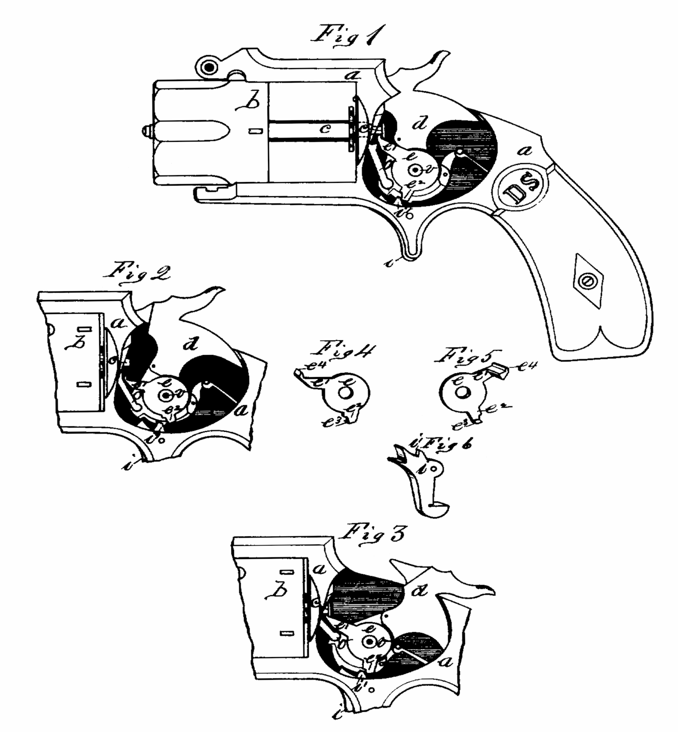
In the drawings, forming part of this specification, Figure 1 is a side elevation of a revolving fire-arm embodying my improvements, in which the barrel and the side plate of the frame are removed, and in which the hammer is shown in the position it is after firing. Fig. 2 is a side elevation showing only that part of the arm in which the hammer is located and parts adjacent thereto, and showing the hammer at half-cock. Fig. 3 is a similar view to Fig. 2, but showing the hammer at fall-cock. Fig. 4 is a front view of the oscillating spindle-catch. Fig. 5 is a rear view of said spindle-catch. Fig. 6 is a view of the trigger of the arm.
Like letters refer to like parts in the several figures.
In the drawings, a is the frame. b is the cylinder. c is the extractor-spindle. d is the hammer. e is an oscillating spindle-catch. o is a pawl, and i is the trigger.
In arms of this class it is desirable to have them constructed with simple and surely-operating automatic devices actuated by the movements of the hammer for holding the extractor-spindle back in the position shown in Fig. 1, while the cylinder is drawn forward to extract the empty cartridge-shells therefrom, and which will also operate to disengage the extractor-spindle immediately that the hammer is slightly drawn back or brought to a half-cock, so that the cylinder and the extractor spindle may be freely removed from the frame. The above-named desideratum is met by the improved construction herein described and shown.
The improvements which are the subject of this application are embodied in the construction of the rear end of the extractor-spindle, and in certain modifications in the construction of the hammer and trigger, whereby the above-named parts and the pawl are adapted to co-operate with a new element of construction to produce the said result, which is designated as the “oscillating spindle-catch.”
The rear end of the extractor-spindle c is made of a reduced diameter just forward of its rear end, so as to form a head thereon, as shown.
The hammer d is made with a circular boss or stud, v, projecting from one side thereof around the hole-through which the hammer-screw passes. Upon said boss or stud v is hung the oscillating spindle-catch e. The said spindle-catch is here shown hung upon the side of the hammer, as above described, as that is the most convenient disposition which can be made of the catch in arms of the description herein shown; but for all purposes of the proper operation of said catch by the pawl o and by the trigger i, as hereinafter described, said catch may as well be hung upon any convenient stud on the frame of the arm. This catch is made in the form shown in the various figures, having an arm, e’, provided with a short sharp hook, e4, at its extremity, and a second arm, e2, provided with a short projection, e3, standing at right angles to said arm e. The trigger i has an upwardly-projecting tooth, i’, upon it. The said spindle-catch e is, as aforesaid, hung upon the boss or stud v upon the side of the hammer d, and when so placed the hook e4 upon the end of arm e’ is in such position that when said catch is turned upon the boss or stud v said hook may engage with and be disengaged from the headed end of spindle c, as shown in Figs. 1 and 2. The arm e2 on the lower edge of said spindle-catch e, reaches down far enough to carry the projection e3 on its lower end within the reach of the upper end of the tooth i’ upon the trigger i.
The operation of the above-described devices to release and to hold the extractor-spindle c is as follows: When the hammer d is moved from the position shown in Fig. 1 to a halfcock the pawl o is moved upward, carrying its upper end beyond the end of arm e’ on catch e, and at about the instant that the end of the pawl reaches said position the sear-tooth of trigger i falls into the half-cock notch on the hammer, throwing the end of tooth i’ on the trigger suddenly against said projection e3 on arm e2 of the spindle-catch e, causing the latter to turn on stud v and throw the end of arm e’ down to the position shown in Fig. 2, thus: disengaging hook e4 from spindle c and leaving the latter free to be drawn out of the frame. When the trigger is disengaged from its half-cock notch in the hammer and the latter is allowed to swing back to the position shown in Fig. 1, the tooth i’ in said trigger swings forward out of the way of arm e2, and the end of pawl o, moving down against the end of arm e’, crowds the latter up against spindle c, causing hook e4 to engage therewith, as shown. It will be seen that when the end of pawl o has been carried up beyond the end of arm e’ on catch e the latter is free to oscillate on stud or boss v, and to let the end of arm e’ drop down by gravitation. This action will generally take place without the aid of the movement of tooth i’ on the trigger against arm e2 on said catch, as above described; but said movement of tooth i’ makes the disengagement of hook e4 from spindle c positive. When the hammer is brought to full-cock, as in Fig. 3, the hook e4 is brought into engagement with the end of the spindle c, carried round by the pawl o, moving up against the under side of arm e’ on the catch e.
What I claim as my invention is—
1. The spindle-catch e, hung at the side of the hammer, and having a hook upon the end of its arm e’ to engage with the headed end of the extractor-spindle, in combination with the pawl o, substantially as and for the purpose set forth.
2. The spindle-catch e, hung at the side of the hammer, and having the arm e’, provided with the hook e4, and the arm e2, in combination with the trigger i, having the tooth i’, substantially as and for the purpose set forth.
3. The oscillating spindle-catch e, constructed substantially as described, swinging upon a suitable pivot or stud within the frame of the arm, combined with and controlled in its movements by the pawl o, and the trigger, substantially as and for the purpose set forth.
DEXTER SMITH.
Witnesses:
H. A. CHAPIN,
J.D. GARFIELD.