
US 14820
UNITED STATES PATENT OFFICE.
GEORGE LEONARD, OF SHREWSBURY, MASSACHUSETTS.
IMPROVEMENT IN REPEATING FIRE-ARMS.
Specification forming part of Letters Patent No. 14,820, dated May 6, 1856.
To all whom it may concern:
Be it known that I, GEORGE LEONARD, of Shrewsbury, in the county of Worcester and Commonwealth of Massachusetts, have invented new and useful Improvements in Fire-Arms; and I do hereby declare that the following is a full and exact description.
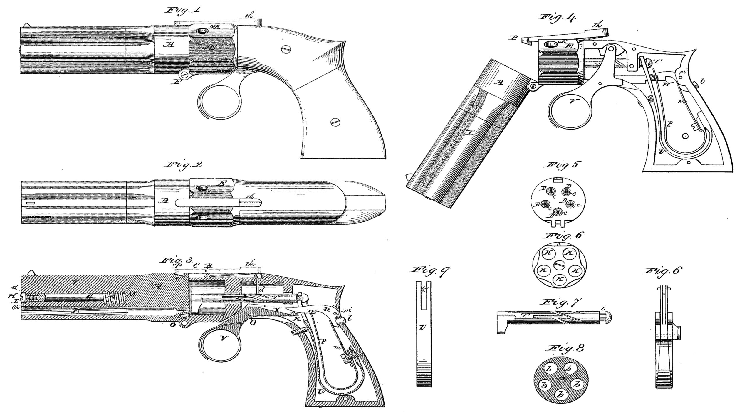
Figure 1 is a side view of a fire-arm containing said improvements. Fig. 2 is a top view of the same. Fig. 3 is a central vertical and longitudinal section of it. Fig. 4 is a side view of it with the side plate and stock detached and the chamber turned down from the breech in a position for capping the cones for cleaning, &c. Fig. 5 is a back view of the chamber. Fig. 6 is a front view of the barrels. Fig. 7 is a side view of the revolving hammer. Fig. 8 is a cross-section of the chamber. It is pierced with five or any suitable number of bores arranged in a circle, b b b b b.
A, Figs. 1, 2, 3, and 4, represents different views of the chamber. The back end of the chamber has five cones, c c c c c, sunk in circular cavities D D D D D, Fig. 5. The chamber is hinged to the breech E, Figs. 1, 3, and 4, as seen at F, Figs. 1, 3, 4; and 5, so that it can be turned down from the breech, as seen in Fig. 4, for the purpose of capping the cones for cleaning, &c. The back of the upper part of the chamber A, Fig. 3, has a locking-recess, o, adapted to receive a catch, P, on the front end of a lever, l c, turning on a fulcrum, R, lying within a recess, o, in the breech, and having a thumb-piece, t h, on the back end. The thumb-piece t h rests upon and is kept up by the upper leaf of a V-spring, s, whose lower leaf, a’, has a stud, d, extending downward through a corresponding aperture in the breech and entering and bearing on the bottom of some one five grooves of a cylindrical shaft of a revolving hammer.
A spindle, G, Fig. 3, is firmly and unalterably screwed into the center or axis of the chamber at M’. It passes through a cylindrical bore or passage, H, in the center of the piece I, composing the barrels K K K K K, Fig. 6, the number of which is equal to that of the bores in the chambers. The back of the spindle G, Fig. 3, projecting from the chamber has a screw, M, a continuation of that at M’, and is adapted to a corresponding nut, N, in the back part of the bore H. A portion of the front of the bore H is made somewhat larger than the back part of it. It is of the same size as the head of the screw L, which is screwed into the front end of the spindle. It has a shoulder, s h s h, at the back part, so that when the barrels are unscrewed at M and N from the chamber they can be slid back on the spindle G until the head of the screw L, which projects on all sides over the spindle, touches the shoulder s h s h and no farther.
In loading, unscrew the barrels at M and N, draw them forward on the spindle G until the head of the screw L strikes the shoulder s h s h, grasp the barrels in the left hand, hold them vertically, and with the right hand turn each bore of the chamber severally into a convenient position and load it, screw down the barrels so that each one may exactly range with its appropriate bore in the chamber, press the thumb-piece t h of the lever l e so as to raise the catch P from the recess o, turn down the chamber, as in Fig. 4, cap the cones, and then return the chamber to its first position. The fire-arm is now loaded.
The central screw, by which the barrels and chamber are attached and disconnected for loading, I admit has been employed for many years. I do not say I was not the original inventor; but I regard it by itself as of little value. When the fire-arm is wholly separated into two parts the liability of dropping one while loading, especially when in a hurry or on horseback, is so great as to preclude the general use of any expedient for such separation; but the combination of the central screw with a spindle having a projecting head, formed in this case by the head of the screw L, this head sliding in a bore of its own size, but larger than that for the spindle, with a shoulder to strike the projection of the head and hinder the barrels from being entirely detached, I regard of great importance, without which this fire-arm would be comparatively valueless.
The hammer T, Figs. 3 and 7, consists of a straight cylindrical shaft, s h a, playing through two apertures in the breech e and f, Figs. 3 and 4, and which has a transverse groove, i, around it near the back part to receive the mainspring U, Figs. 3 and 4, and allow it to work a beak, b c, Figs. 3 and 7, which by the continued operation of the fire-arm is revolved and struck against each cap successively until all are exploded.
The expedients for guiding and revolving the hammer are as follows: Five or any suitable number of equidistant longitudinal grooves, g g, Fig. 7, are sunk in the surface of the shaft. These are crossed in the proper places at a suitable acute angle by an equal number of equidistant oblique grooves, h h h. The bottom of the front part of the straight grooves is sunk deeper into the shaft than the bottom of the corresponding part of the oblique grooves, and the bottom of the back part of the oblique grooves is sunk deeper into the shaft than the bottom of the corresponding part of the straight grooves. The direct and rotary motions of the hammer are actuated as follows: When the fire-arm is in its usual position, Fig. 3, the stud d is pressed by the spring s to the bottom of the back part of an oblique groove. In cocking, the hammer is drawn back and the stud d, following the oblique groove, partially rotates the hammer until the stud reaches the straight groove, to the bottom of which it is instantly driven by the spring s. In discharging, the hammer is driven forward and the stud d, following the straight groove keeps the beak of the hammer in the proper position, until just before it strikes the cap the stud reaches the next oblique groove, into which it is instantly driven by the spring s, and so on.
The preceding method of effecting the direct and rotary motions of a shaft or hammer I do not consider new. I used a similar method, as well as some others, many years ago to produce the same motions in long runner-drills worked by double iron brakes. The device was not then new to me. The breech of a chambered fire-arm manufactured at Windsor, Vermont, about twenty years ago, was retracted, rotated, and guided in its forward motion by this identical expedient. It is now in existence, and was made in a large armory, so that all the circumstances attending its construction are well known. The same contrivance has been used for some years in some sewing-machines, the models of which, I presume, are at Washington. Neither do I assert any invention or originality in my use of several concentric barrels in fire-arms. Though their long-continued use is undoubted, it may be well to admit that I have reason to believe they were manufactured in this town fifty years ago. They were made by Edwin Wesson, then of this town, more than twenty years ago, and by Ethan Allen, now of the firm of Allen & Thurber, of Worcester, more than fifteen years ago; but I do regard the machine or fire-arm made by a combination of a hammer constructed and operated as before stated, with several concentric barrels, as quite new and original with me. Such a hammer without a series of concentric barrels could never be made into a machine or fire-arm like the one in question, or with similar properties or advantages.
The mainspring U, Figs. 3 and 4, is bifurcated at the top, as seen in its front view at k, Fig. 9, and is hooked into the groove i of the hammer. The trigger V, Figs. 3 and 4, is carried by and turns upon the pin in the cocking-lever X, which cocking-lever turns on the pivot O. In the operation of cocking, the cocking-lever carries back the trigger by means of the pin n, and forces a notch, n o, Fig. 3, near its back part, on its under side, against the main-spring, which is carried back until the catch W of the sear s e, Figs. 3 and 4, drops and catches it at k’ Fig. 9, and holds it firmly in a cocking position. The-sear previous to catching the mainspring enters a slot in the center of the back part of the trigger, as seen in a top view of the trigger, Fig. 10. The catch W of the sear s e, Figs. 3 and 4, is kept down by the operation of the sear-spring m, which presses against it below the pivot p i. The sear has a thumb-piece, l, projecting through the back part of the breech. If said thumb-piece be pressed against by the thumb and the cocking-lever be gradually eased down by the finger, the fire-arm can be uncocked without discharging it.
The fire-arm is discharged by drawing the trigger, which raises the bottom of the slot b, Fig. 10, in its back end against the front end of the sear, and disengages the catch of the sear from the mainspring. After the mainspring has driven forward the hammer the trigger and cocking-lever are carried forward by the trigger-spring P, Figs. 3 and 4, which presses against the back part of the trigger.
From the preceding it appears that the fire-arm cannot be uncocked by drawing the trigger and easing down the cocking-lever. The trigger contributes to the operation of uncocking only so far as it has some of the properties of a cocking-lever, as it has when cocking and uncocking in the notch n o and in its connection with the cocking-lever by the pin n. On the combination of a cocking-lever and trigger with properties similar to those just stated I have now a patent. A sear with qualities like the one in question may not be new, but a combination of this sear with a cocking-lever and trigger having the properties as stated I regard as a new and original invention and indispensable to the efficiency of this fire-arm. Without the sear the cocking-lever must be held back by one finger while the trigger is drawn by another. This was the construction used by me in a large lot of pistols. Without the exterior thumb-piece, 1, Figs. 3 and 4, the fire-arm cannot be uncocked without discharge; and if the trigger had the usual properties, and only the usual properties, which it has in a musket, rifle, or pistol, no such sear with an exterior thumb-piece would be required to uncock the fire-arm.
1. I do not claim the invention of a central screw by which several concentric barrels may be attached to and disconnected from a chamber with a proper number of bores; but I claim the invention, in fire-arms, of an expedient for connecting several concentric barrels to a chamber having an equal number of bores, and for partially but not wholly disconnecting the same for the purpose of loading, cleaning, &c., consisting of a combination of a central screw with a spindle having a projecting head, and a bore of two different diameters in the center of the concentric barrels, the front part of the bore being larger than the back part and of the diameter of the projecting head, and the back part of the bore being smaller than the front part and of the diameter of the spindle, the whole to be constructed substantially as herein described, but independent of any accidental properties.
2. I do not claim the invention of a revolving hammer for fire-arms of any peculiar construction, or the invention of any device or expedient to regulate its motions. Neither do I claim the invention, in fire-arms, of several concentric barrels, nor of several concentric barrels having anything special or peculiar in their construction; but I claim the invention, in fire-arms, of a combination of several concentric barrels with a revolving hammer for their successive discharge, the reciprocating and revolving motions of which hammer are governed and guided by straight and oblique grooves sunk in its surface, each kind of groove to be equal in number to the barrels; the whole to be constructed substantially as herein described, but independent of any accidental properties.
3. I do not claim the invention, in fire-arms, of a sear having a thumb-piece or arm projecting beyond the breech or stock, so that the fire-arm may be uncocked by pressing on said thumb-piece or arm and easing down the hammer; but I claim the invention, in fire-arms, of a combination of a cocking-lever, trigger, and sear with a thumb-piece, the combination to have such characteristics that the fire-arm can be uncocked without discharge only by pressing said thumb-piece and easing down said cocking-lever, the whole to be constructed substantially as herein described, but independent of any accidental properties.
In testimony whereof I, the said GEORGE LEONARD, hereto subscribe my name, in the presence of the witnesses whose names are written below, on this 1st day of February, A. D. 1856.
GEORGE LEONARD.
In presence of—
JOB C. STONE,
MARY A. TYLER.