
US 198745
UNITED STATES PATENT OFFICE.
OWEN JONES AND FRANK W. MARSTON, OF PHILADELPHIA, PENNSYLVANIA.
IMPROVEMENT IN EXTRACTORS FOR REVOLVING FIRE-ARMS.
Specification forming part of Letters Patent No. 198,745, dated January 1, 1878; application filed June 6, 1877.
To all whom it may concern:
Be it known that we, OWEN JONES and FRANK W. MARSTON, of Philadelphia, in the county of Philadelphia and State of Pennsylvania, have invented. a new and useful Improvement in Cartridges and Extractors; and we do hereby declare that the following is a full and exact description of the same, reference being had to the accompanying drawing, and to the letters of reference marked thereon.
This invention consists, mainly, in the combination of certain independent mechanism for extracting the cartridge-shells with certain independent mechanism for changing the shape or position of a portion of the cartridge-shell to bring it within the range of the extracting mechanism.
It consists, further, in certain details of construction, which, in connection with the foregoing, will be fully described hereinafter.
A general statement of the method may be made, as follows: The cartridges having been first arranged in the cylinder in such manner as to be entirely independent of the extractor, but in close proximity thereto, are then successively exploded in the usual manner by the impact of the hammer. By this impact, also, a portion of the cartridge-shell is forced out of its normal shape or position, and caused to engage with the extractor, so that when the proper devices are actuated it may be thrown out in the usual manner.
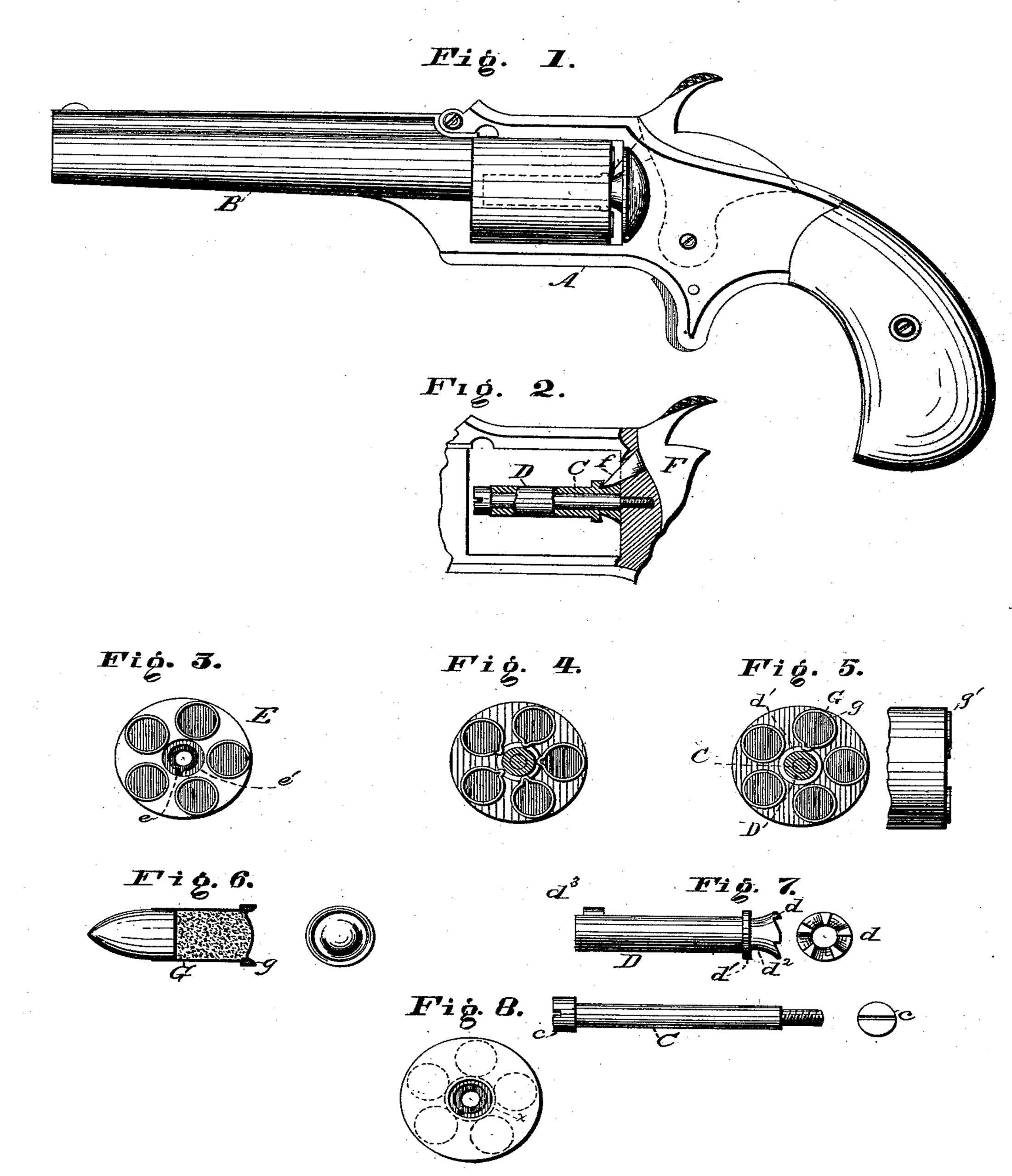
In the drawings, Figure 1 represents a side elevation of a pistol having our improvements applied thereto; Fig. 2, a partial side elevation of the frame, with the extractor-sleeve partially in section; Fig. 3, an end elevation of the cylinder, with the cartridges in place; Fig. 4, a similar view after all the cartridges have been exploded; Fig. 5, a similar view with one cartridge only exploded; Fig. 6, views of the cartridge enlarged; Fig.7, views of the extractor-sleeve and center-pin; and Fig. 8, an end elevation of the cylinder, in which the cartridges are shown, separated from the extractor, by a dotted circle.
To enable others skilled in the art to use our method, and the devices employed in connection therewith, we will now proceed to describe the same fully, and the construction and operation of the devices.
A represents the frame of the pistol, and B the barrel, which may be constructed generally in the usual well-known or other proper manner. C, Figs.2 and 7, represents a center-pin, projecting forward from the frame a proper distance, which is screwed into place in the usual manner, and is provided with the head c, as shown. D represents a sleeve, located on the pin, between the head c and the frame, which is adapted to turn freely thereon, and is provided at its extreme rear end with a ratchet-face, d, and adjacent thereto with an annular flange or shoulder, d’, and an annular groove or recess, d2. d3 represents a stud or projection near its front end, by means of which rigid connection is made with the cylinder, as far as revolution is concerned, without affecting the freedom of its longitudinal movement. E represents the cylinder, constructed generally in the usual well-known or other proper manner, but provided with a longitudinal groove or recess, e, and an annular recess, e’, at its rear end. F represents the hammer, which is constructed generally in the usual manner, and operated in the ordinary way; but which is provided with an exploding point, f, so arranged as to strike, when released by the trigger, behind the shoulder d’ of the extractor-sleeve down into the recess d2, as shown in Fig. 2. G, Fig. 6, represents the cartridge-shell, which may be of the usual well-known construction, but which is preferably provided with an auxiliary flange or projection, g, extending in a rearward direction, as shown.
This special cartridge is not claimed per se in this connection, as it will be made the subject of a separate application for a patent.
When the parts are in their proper position, as shown in Fig. 3, it will be observed that the cartridges and the extracting device are located in independent planes, and that the former are not either in contact with the latter, or within the line of its action, the annular flange of the extractor occupying a central space, which lies wholly within the circle in which the cartridges are located, as shown in Fig. 8.
The operation will be readily understood.
The pistol, after having been properly loaded, may be fired in the usual manner.
By the descent of the hammer the cartridge, of course, is exploded; but in addition, also, to this result, a portion of the flange is turned over into the recess d2 behind the shoulder or flange of the extractor, as shown in Figs. 4 and. 5. In consequence of this change of shape or position it follows that when the cylinder is drawn forward the shell cannot move with it, because it is held by the contact of its projecting portion with the fixed shoulder; hence the shell may be extracted by simply drawing the cylinder away from it in the usual well-known manner.
It will be observed that only the shells which are struck by the hammer will be caused to engage with the extractor, and hence that, in the act of extracting, loaded shells will never be disturbed under any circumstances. If desired, the ordinary shell may be employed; but the form shown, or some equivalent form, is preferred. A rim-fire cartridge also is preferred; but, if desired, a central fire cartridge may be used by adding to the hammer a proper projection to explode the same.
This invention is especially adapted for that class of revolvers covered by Owen Jones’ patents of June 20, 1876, No. 179,026, and April 10, 1877, No. 189,360; but it may be applied also to the Smith & Wesson extracting-revolvers, if desired, and to any others of suitable construction.
We do not limit ourselves to the use of the hammer for upsetting the metal of the cartridge, as auxiliary mechanism may be employed for this purpose.
Having thus fully described our invention, what we claim as new, and desire to secure by Letters Patent, is—
1. The combination of the following elements: Independent mechanism, substantially as described, for extracting the cartridge-shells, and. independent mechanism, substantially as described, for changing the shape or position of a portion of the cartridge-shell to bring it within the range of action of the extracting mechanism.
2. The combination of the following elements: An independent extractor, a cylinder, substantially as described, adapted to hold the cartridge out of the line of action of the extractor, and mechanism, substantially as described, adapted to act on the rim of the shell and cause it to engage with the extractor.
3. In combination with the cylinder E, the extractor D and the hammer F, substantially as described.
4. In combination with the cylinder and its center-pin, the extractor-sleeve or equivalent device, and the hammer, adapted to change the shape of the cartridge-shell, substantially as described.
5. An independent extractor, lying out of the plane of the cartridges, having a recess adapted to receive the projecting portion of a shell after the form of the shell has been changed, as set forth.
6. In combination with an extractor lying out of the plane of the cartridge, and having a recess, a hammer-head adapted to enter the recess, as and for the purpose set forth.
7. The combination of the following elements: A cylinder adapted, substantially as described, to hold a series of cartridges out of the line of action of the extractor, a central extractor adapted to receive the projection of all the cartridges of the series after the forms of the shells have been changed, and mechanism, substantially as described, for changing the position or form of the rims of the cartridges.
8. The method described of extracting cartridge-shells, consisting, essentially, first, in locating a series of cartridges in the cylinder in a circle concentric with a central extracting device, but out of the line of the extractor’s action; second, changing the shape or position of the rims of two or more cartridges, when the latter are exploded, to bring them within the range of the extractor’s action; and, third, actuating the extracting device to simultaneously remove all the exploded cartridges.
This specification signed and witnessed this 4th day of June, 1877.
OWEN JONES,
FRANK W. MARSTON.
Witnesses:
E. P. CLEMENCE,
BK. H. ECKFELDT.