
US 163036
UNITED STATES PATENT OFFICE.
DANIEL B. WESSON, OF SPRINGFIELD, MASSACHUSETTS.
IMPROVEMENT IN REVOLVING FIRE-ARMS.
Specification forming part of Letters Patent No. 163,036, dated May 11,1875; application filed January 26, 1875.
To all whom it may concern:
Be it known that I, DANIEL B. WESSON, of Springfield, in the State of Massachusetts, have made a new and useful invention of an Improvement in Revolving Fire-Arms; and that the following is a full, clear, and exact description and specification of the same.
The object of my invention is to extract all the shells at once from the chambers of the cylinder of a revolving firearm; and to this end it consists of an extractor-plate provided at the rear side with a projection extending to, and having its bearing in which it revolves wholly in, the rear of the front face of the recoil-shield, said projection being provided with ratchet-teeth to rotate it, and with an annular groove, by means of which, in connection with a pin or catch, the extractor is held while the shells are being extracted from the cylinder as the recoil-shield and cylinder are being moved apart. The front of the extractor-plate is provided with a prismatic stem, which, when the cylinder and recoil-shield are moved together again, enters a corresponding prismatic hole in the cylinder, by which the rotary movement of the extractor is communicated to the cylinder.
In order that the invention may be fully understood, I will describe it, having reference to the figures in the accompanying drawing, and to the letters of reference marked thereon.
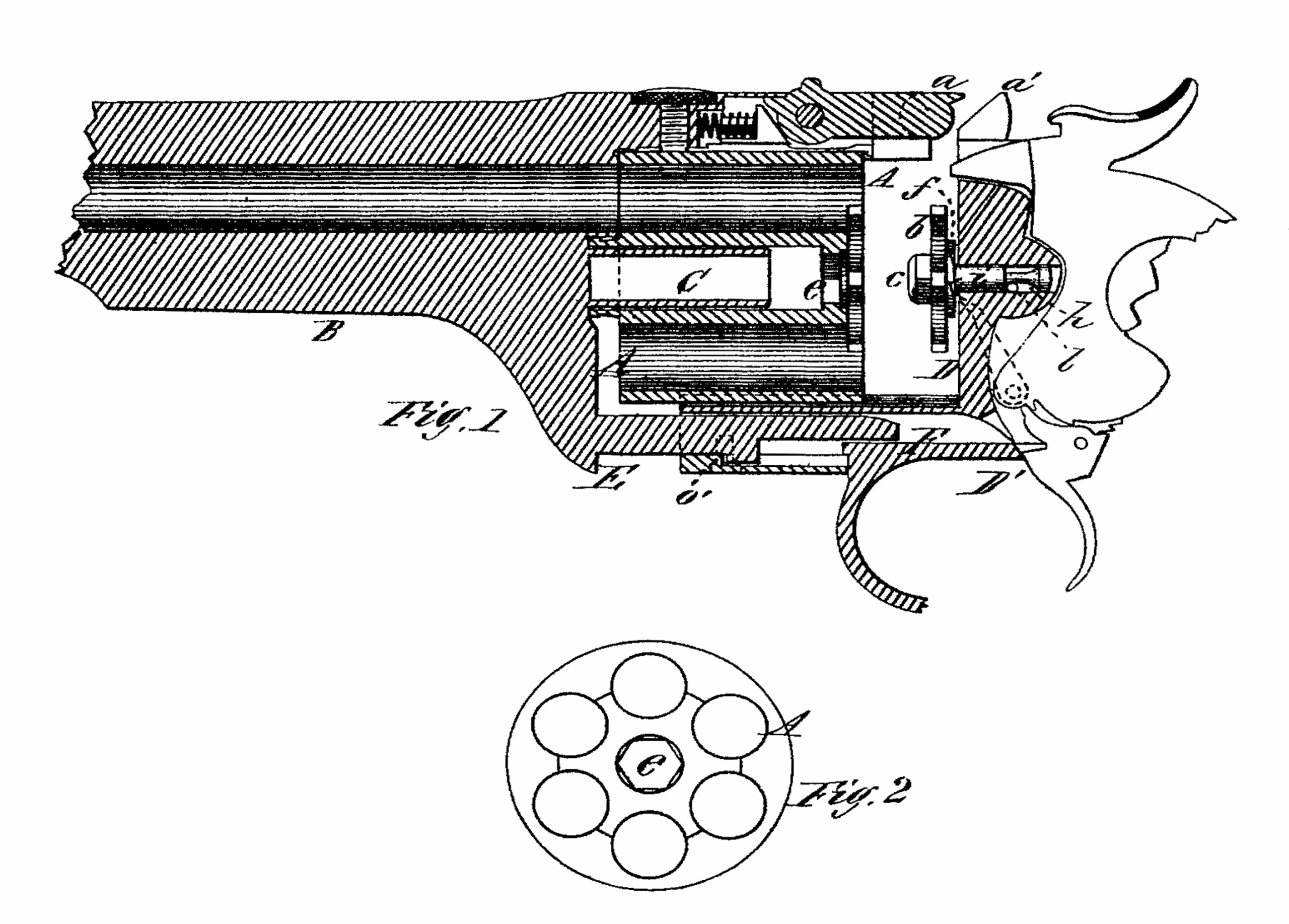
Figure 1 is a central vertical longitudinal section of a revolving fire-arm having my invention applied thereto, and Fig. 2 is a rear end view of the cylinder.
A represents the cylinder, having any desirable number of chambers, and is secured to and rotates upon the center-pin C, made upon the rear end of the barrel B, and the rear end of the cylinder is provided with a central hole, having any desirable number of sides, but preferably the same number as there are chambers in the cylinder. b is the extractor-plate, provided on its rear side with the stem i, which extends back into the central hole in the recoil-shield D, which stem has its bearing, upon which the extractor revolves, wholly in the rear of the front face of the recoil-shield D. This stem is provided with an annular groove, h, through which extends a pin, l, inserted into the recoil-shield, or through a projection in its rear, and said groove is somewhat elongated to allow a little longitudinal play of the stem. The rear side of the extractor-plate b is also provided with a ratchet, f, with which the dog upon the hammer engages to rotate the extractor-plate as the hammer is pulled back. Upon the front of the extractor-plate is made a prismatic projection, having the same number of sides as the hole e in the rear end of the cylinder A, so that when the cylinder is forced back against the extractor-plate the projection c will enter the hole e, and fit it sufficiently well to cause the cylinder to rotate whenever the extractor is rotated. The lower forward part of the frame D’ is provided with a sleeve, F, in which slides, in a longitudinal direction, the arm E, made upon the lower rear part of the barrel, and the sleeve may be provided inside with a shoulder, o, and the arm may be provided with a stop, both arranged to limit the longitudinal movement of the barrel and cylinder; or this movement may be limited by any other desirable and convenient means.
The operation of my invention is as follows: When the cylinder is in its position against the recoil-plate the cartridges may be inserted into the chambers of the cylinder at the side of the arm, the heads or flanges of the cartridges being in the rear or outside of the extractor-plate, and as the hammer is cocked in the operation of firing the dog upon the lower end of the hammer engages with the ratchet-teeth f upon the rear of the extractor-plate b, and rotates it, and its rotating motion is communicated to the cylinder by the prismatic projection on the front of the extractor-plate fitting into the corresponding hole e in the rear end of the cylinder. After the cartridges are all fired the latch a, which secures the barrel to the frame, is disengaged from the top a of the recoil-plate, and the barrel and the cylinder secured thereto are moved forward by drawing the arm E partially out of the sleeve F, until it is stopped by the shoulder o, As the cylinder is thus being drawn forward, the extractor b, in general terms, remains stationary, and the shells are all drawn from the chambers of the cylinder. I find it preferable, however, to permit the extractor b to have a slight longitudinal movement, and as the shells are drawn the extractor is drawn slightly forward out of its bearing in the recoil-plate, according to the width of the annular groove h. By this slight longitudinal movement of the extractor the shells are caused to free themselves from the extractor more quickly, and drop out of the way, than if the extractor were positively permanent in its longitudinal position.
It will be seen that as thus constructed the cylinder always moves with the barrel, being made fast thereto, and the extractor is operated entirely from the rear, which permits greater simplicity and accuracy in the construction of the barrel and cylinder.
What I claim as my invention is—
1. In combination with a lock-frame, a single barrel, and a revolving cylinder of chambers, an extractor so arranged that the bearing upon which it revolves is wholly in rear of the front face of the recoil-shield.
2. In combination with a single barrel and revolving cylinder of chambers, a revolving extractor having a central shaft or other projection extending in a rearward direction from the front face of the recoil-shield, for the purpose of holding the said extractor, for withdrawing the cartridge-shells from the said chambers.
DANIEL B. WESSON.
Witnesses:
T. A. CURTIS,
M. B. HALL.