
British 768
LETTERS PATENT to Joseph Bentley, of Liverpool, in the County of Lancaster, Gun Manufacturer, for the Invention of “ Improvements in Breech-loading Fire-arms.”
Sealed the 26th September 1854, and dated the 4th April 1854.
PROVISIONAL SPECIFICATION left by the said Joseph Bentley at the Office of the Commissioners of Patents, with his Petition, on the 4th April 1854.
I, Joseph Bentley, of Liverpool, in the County of Lancaster, Gun Manufacturer, do hereby declare the nature of the said Invention for “ Improvements in Breech-loading Fire-arms ” to be as follows :—
To construct (say) a gun according to this Invention, the lower limb of the hammer is elongated, so as to extend below the lock frame a little in front of the trigger; by which arrangement, when the lower end is pressed forward (which can be instantly done by the thumb of the left hand), the hammer receeds back to half or full cock at pleasure. The hammer is attached by a swivel link to the main spring; the lower front end of* the main spring also acts as a spring to force and keep the trigger into notches formed in the base of the hammer, and by which it is held up. The chambers are caused to revolve by means of a small lever (connected by a pin to the side of the hammer, and) working (within a recess in the inside of the stock frame) against a toothed ratchet formed on the back of the revolving chambered breech> in the same way as described by the applicant in a Specification of a Patent granted to him, dated 4th December 1852.
The chambers are securely held in their position when the gun is on full cock, and until the point of the hammer has been in contact with the nipple and returned to half cock by a small lever bolt or stop, which works in a recess or groove formed in the stock frame immediately below the chambers. This stop bolt consists of a small piece of metal working on a transverse pin, about two-thirds of its length from the front end. On the upper side of the front end there is a projection, which takes into recesses formed in the surface of the revolving chambers, into which it is pressed by a small spring placed beneath that end; the near or reverse end is turned upwards to about one-fourth the height of the entire length of the lever ; upon the back of the top of the portion turned up, a catch or projecting notch is formed, and which is used to lift that end of the lever and consequently depress the other, so that the projecting stop upon the top of the other end is withdrawn from the recess in the rotating chambers to allow them to revolve, and bring the next chamber into a position to be discharged, the catch taking into the next notch, and so on. This stop or chamber bolt is withdrawn from the recesses in the revolving breech by means of a “ pall ” (or small piece of metal)’jointed to the front of the lower limb of the hammer, and which is provided with a spring at the back, so that it can yield in a backward direction to allow it to pass the projecting notch on the back of the chamber bolt, when by the action of the hammer it is carried below it, when it is ready to press it up on the next upward action of the hammer. When the hammer arrives at a little past half cock, they (the pall and chambers bolt) disconnect themselves, so that the near end of the chamber lever bolt is again pressed downwards by the action of the spring under the outer end, pressing up that end against the revolving chambers and into one of the recesses cut therein, when it arrives just above it, and remains there until the piece is discharged and the hammer is again brought back.
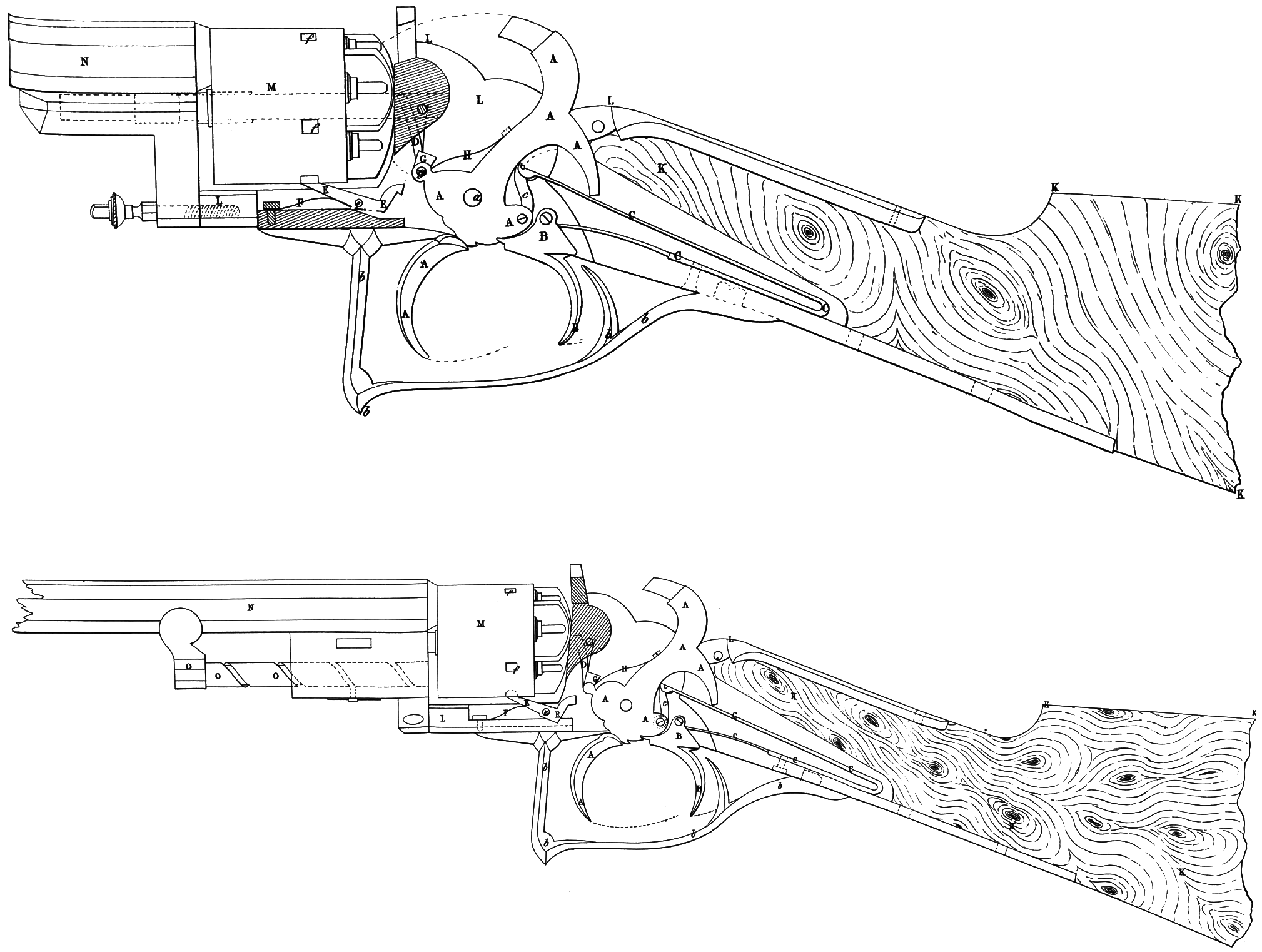
That the foregoing description may be the more readily understood, annexed is a Drawing (partially in section), showing this Invention applied to a gun. Like letters refer to similar parts. A, the hammer (or cock) working on its pin at a. B, the trigger; 5, the trigger guard. C, the main spring, with its lower front end acting as a spring to keep the trigger in position, and connected to the hammer by the swival link c. D, a pall or lever (jointed to the lower h*mb of the hammer), for causing the chambers to rotate by acting upon a ratchet on the back of the chambers; d, a spring to keep the lever to its work. E, the lever stop or bolt, by which the chambers are securely held during the act of fireing, and working on a transverse pin at e. F, spring, to press the outer end of the breech bolt upwards. /, recesses formed in the breech, to receive the projection upon the top of the bolt E. G, a small pall or lever (jointed to the hammer by a pin at g), to press upwards the near end of the lever E. H, a spring1, to allow the pall G to yield a little backwards in passing the projection on the back of the chamber bolting lever E. 5 K, the stock (partially shown). L, the stock frame (partially in section). M, rotating breech. N, barrel, partially shown.
SPECIFICATION in pursuance of the conditions of the Letters Patent, filed by the said Joseph Bentley in the Great Seal Patent Office on the 3rd October 1854.
TO ALL TO WHOM THESE PRESENTS SHALL COME, I, Joseph Bentley, of Liverpool, in the County of Lancaster, Gun Manufacturer, send greeting.
WHEREAS Her most Excellent Majesty Queen Victoria, by Her Letters Patent, bearing date the Fourth day of April, in the year of our Lord One thousand eight hundred and fifty-four, in the seventeenth year of Her reign, did, for Herself, Her heirs and successors, give and grant unto me, the said Joseph Bentley, Her special license that I, the said Joseph Bentley, my executors, administrators, and assigns, or such others as I, the said Joseph Bentley, my executors, administrators, and assigns, should at any time agree with, and no others, from time to time and at all times thereafter during the term therein expressed, should and lawfully might make, use, exercise, and vend, within the United Kingdom of Great Britain and Ireland, the Channel Islands, and Isle of Man, an Invention for “ Improvements in Breech-loading Fire-arms,” upon the condition (amongst others) that I, the said Joseph Bentley, by an instrument in writing under my hand and seal, should particularly describe and ascertain the nature of the said Invention, and in what manner the same was to be performed, and cause the same to be filed in the Great Seal Patent Office within six calendar months next and immediately after the date of the said Letters Patent.
NOW KNOW YE, that I, the said Joseph Bentley, do hereby declare the nature of my said Invention, and in what manner the same is to be performed, to be particularly described and ascertained in and by the following statement, reference being had to the Drawing thereunto annexed, and to the letters marked thereon (that is to say):—
To construct a gun according to this Invention, the lower portion or limb of the hammer is elongated, so as to extend below the lock frame (or body) a little in front of the trigger; by which arrangement, when the lower end is pressed forward (which can be instantly done by the thumb of the left hand), the hammer receeds back to half or full cock at pleasure. The hammer is attached by a swivel link to the mainspring; the lower front end of main spring also act as a spring to force and keep the trigger into notches formed in the base of the hammer, and by which it is held up.
The chambers are caused to revolve by means of a small lever, connected by a pin to the side of the hammer, and working within a recess in the inside of the stock frame against a toothed ratchet formed on the base of the revolving chambered breech (in the same way as described in a Specification of a Patent granted to me, dated the Fourth December 1852).
The chambers are securely held in their position when the gun is on full cock, and until the point of the hammer has been in contact with the nipple and returned to half cock, by a small lever bolt or stop, which works in a recess or groove formed in the stock frame immediately below the chambers. This stop bolt consists of a small piece of metal working on a transverse pin, about two-thirds of its length from the front end ; on the upper side of the front end there is a projection which takes into recesses formed in the surface of the revolving chambered breech, into which it is pressed by a small spring placed beneath that end; the near or reverse end is turned upwards to about one-fourth the height of the entire length of the lever. Upon the back of the top of the portion turned up, a catch or projecting notch is formed, and which is used to lift that end of the lever, and consequently depress the other, so that the projecting stop upon the top of the other end is withdrawn from the recess in the rotating chambers, to allow them to revolve and bring the next chamber into a position to be discharged, the catch taking into the next notch, and so on. This stop or chamber bolt is withdrawn from the recesses in the revolving breech by means of a pall,” or small piece of metal, jointed to the front of the body of the hammer, and which is provided with a spring at the back, so that it can yield in a backward direction to allow it to pass the projecting notch on the back of the chamber bolt, when by the action of the hammer it is carried below it, when it is ready to press it up on the next upward action of the hammer. When the hammer arrives at a little past half cock, they (the “ pall and chamber bolt) disconnect themselves, so that the near end of the chamber lever bolt is again pressed downwards by the action of the spring under the outer end, pressing up that end against the revolving chambers and into one of the recesses cut therein, when it arrives just above it, and remains there until the piece is discharged and the hammer is again drawn back. Beneath the barrel and immediately in front of the lower portion of the revolving chambers, I place a short ramrod, having a screw formed upon it, and which works through a hole formed in the metal, by which the barrel is attached to the stock frame. The ramrod has a short lever attached to its outer end, by which it is worked. The chamber to be rammed being brought in front of the end of the rod, the charge is forced home by merely giving the rod a short turn. ’
That this Invention may be the more clearly seen and understood, I have hereunto annexed a Drawing (partially in section) of so much of a gun as will be requisite to show the application of my improvements to a gun. My invention is equaUyj&pplicable to repeating fire-arms in general. Like letters relate to similar parts.
A, the hammer or cock (working on its pin at a\ having the lower portion (or limb) formed to extend below the stock frame. The piece is cocked or placed at half cock, and the revolving chambers brought in rotation opposite to the bore in the barrel of the gun ready to be discharged, upon the lower limb of the hammer being pressed forward, which can be instantly done by the thumb of the left hand, and without taking the gun from the shoulder. B, the trigger; b, trigger guard. C, the main spring, with its lower front end acting as a spring to keep the trigger in position, and connected to.the hammer by the swivel link c. D, a “ pall ” or lever, jointed to the front of the body of the hammer, for causing the chambers to rotate by acting upon a ratchet on the back of the chambers; d, a spring to keep the lever to its work. E, the lever stop or bolt, by which the chambers are securely held during the act of firing, and working on a transverse pin at e. F, spring, to press the outer end of the breech bolt upwards. /, recesses formed in the breech, to receive the projection upon the top of the bolt E. G, a small “ pall ” or lever (jointed to the hammer by a pin at g), to press upwards the near end of the lever E. H, a spring, to allow the palL G to yield a little backwards in passing the projection on the back of the chamber bolting lever E. K, the stock (partially shewn). L, the stock frame, partly in section. M, rotating breech. N, barrel (partially shewn). 0, screw ramrod, place to work beneath the barrel, so that the chambers can be brought in rotation opposite the end of the rod.
Having now described my Invention, and in what maimer the same may be performed, what I claim is,—
First, the application to breech-loading fire-arms of the hammer (or cock) having the limb or “ comb ” formed to extend below the stock frame, as hereinbefore described.
Secondly, the use of a screw ramrod, as herein-before described.
Thirdly and lastly, the general arrangements and combination of the various parts to form a lock suitable for repeating fire-arms, as herein-before described.
In witness whereof, I, the said Joseph Bentley, have hereunto set my hand and seal, this Second day of October, in the year of our Lord One thousand eight hundred and fifty-four.
JOSEPH (l.s.) BENTLEY.
Witness,
William Walker.