
British 955
Filed for Lefaucheux
Revolving Fire-arms.
LETTERS PATENT to John Henry Johnson, of 47, Lincoln’s Inn Fields, in the County of Middlesex, and of Glasgow, North Britain, Gentleman, for the Invention of “ Improvements in Revolving Fire-arms.”—A communication.
Sealed the 27th June 1854, and dated the 27th April 1854.
PROVISIONAL SPECIFICATION left by the said John Henry Johnson at the Office of the Commissioners of Patents, with his Petition, on the 27th April 1854.
I, John Henry Johnson, of 47, Lincoln’s Inn Fields, in the County of Middlesex, and of Glasgow, North Britain, Gentleman, do hereby declare the nature of the said Invention for “Improvements in Revolving Fire-arms ” to be as follows:—
This Invention relates to that class of fire-arms known as “ revolvers,” and consists principally of improvements in the construction of the revolving charge chamber, and in the construction of the breech, whereby greater facility of loading is effected. The revolving chamber is composed simply of a cylinder, with a number of holes or charge chambers bored through it, and also a hole through the axial centre line of the cylinder, for the purpose of attaching it to the body of the pistol. The charge chambers may be bored slightly conical, if required; each chamber is notched at its hind part, to allow of the entrance therein of the percussion cap of the cartridge. The breech of the fire-arm is made in the form of a hemisphere, with a groove or channel in the centre, to admit of the lowering of the hammer, and one side is fitted a moveable door working on a fixed centre in the breech ; this door is opened or shut down by means of a small projection formed upon its surface, and serves to allow of the introduction of the cartridges as fast as the several chambers come round. The rubbing surfaces of the revolving cylinder and the breech are rendered perfectly flat, as the breech serves as a bearing for the back of the cylinder. On the side of the barrel is fitted in suitable slides a flat bolt, which serves to force out the cartridge when not wanted for immediate use or for cleaning the chamber; this bolt may be actuated by hand, each chamber being brought successively opposite to it. The movement of the cylinder is effected as usual, by the cocking of the lock, a projecting catch being made to act upon a ratchet. The cylinder is retained or held in its place by a spring, which drops into a recess or notch on the side of each chamber.
SPECIFICATION in pursuance of the conditions of the Letters Patent, filed by the said John Henry Johnson in the Great Seal Patent Office on the 27th October 1854.
TO ALL TO WHOM THESE PRESENTS SHALL COME, I, John Henry Johnson, of 47, Lincolns Inn Fields, in the County*of Middlesex, and of Glasgow, North Britain, Gentleman, send greeting.
WHEREAS Her most Excellent Majesty Queen Victoria, by Her Letters Patent, bearing date the Twenty-seventh day of April, in the year of our Lord One thousand eight hundred and fifty-four, in the seventeenth year of Her reign, did, for Herself, Her heirs and successors, give and grant unto me, the said John Henry Johnson, Her special license that I, the said John Henry Johnson, my executors, administrators, and assigns, or such others as I> the said John Henry Johnson, my executors, administrators, or assigns, should at any time agree with, and no others, from time to time and at all times thereafter during the term therein expressed, should and lawfully might make, use, exercise, and vend, within the United Kingdom of Great Britain and Ireland, the Channel Islands, and Isle of Man, an Invention for u Improvements in Revolving Fire-arms,” a communication from abroad, upon the condition (amongst others) that I, the said John Henry Johnson, by an instrument in writing under my hand and seal, should particularly describe and ascertain the nature of the said Invention, and in what manner the same was to be performed, and cause the same to be filed in the Great Seal Patent Office within six calendar months next and immediately after the date of the said Letters Patent.
NOW KNOW YE, that I, the said John Henry Johnson, do hereby declare the nature of the said Invention, and in what manner the same is to be performed, to be particularly described and ascertained in and by the following statement, reference being had to the accompanying Drawings, and to the letters and figures marked thereon, that is to say:—
The said Invention relates to the class of fire-arms termed revolvers, and consists chiefly of an improved construction of revolving chambered cylinder, and of a new arrangement of breech, to facilitate of the loading of the weapon. The revolving piece is a cylinder, with six or any other convenient number of cylindrical or slightly conical holes bored through it, to form the charge chambers; an additional hole is bored centrally through the cylinder for the passage of the spindle, upon which it turns, and to which the barrel of the weapon is attached. The charge chambers are each notched through to the outside of the cylinder at their back edges to suit the particular description of cartridge employed, this cartridge being made up with the percussion appliance, attached in such a manner as to enter and project through the notch of the charge chamber. The breech of the weapon is hemispherical in shape, and is formed with a vertical groove, in which the hammer works, the hammer rising up centrally from the stock. The face of the breech piece is perfectly smooth and flat, as is also the end of the charge cylinder in contact with it. A channel is formed in the breech on one side, through which the cartridges are to be introduced into the charge chambers as these are brought round in succesion, and a filling-up piece is hinged to the breech to close the channel when the chambers are not being charged, a spring catch being provided to keep the filling-up piece closed when necessary. In a slide on one side of the barrel, and in a line with the charging channel in the breech piece, is a rod for forcing out the cartridges, if required, without exploding them, or for removing any matters left in the charge chambers after a discharge; this rod is prevented by a blade spring from falling out or moving unless the hand is applied. The rotation of the charge cylinder is effected in the usual way by the action of a catch in connection with the hammer upon a ratchet formed upon the cylinder, and the cylinder is retained accurately in position during each discharge by means of a catch also acted upon by the hammer, and made to enter a notch in the cylinder face after each rotative movement. And in order that the said Invention may be properly understand, I shall now proceed to describe the several explanatory Figures on the Sheet of Drawings hereunto attached.
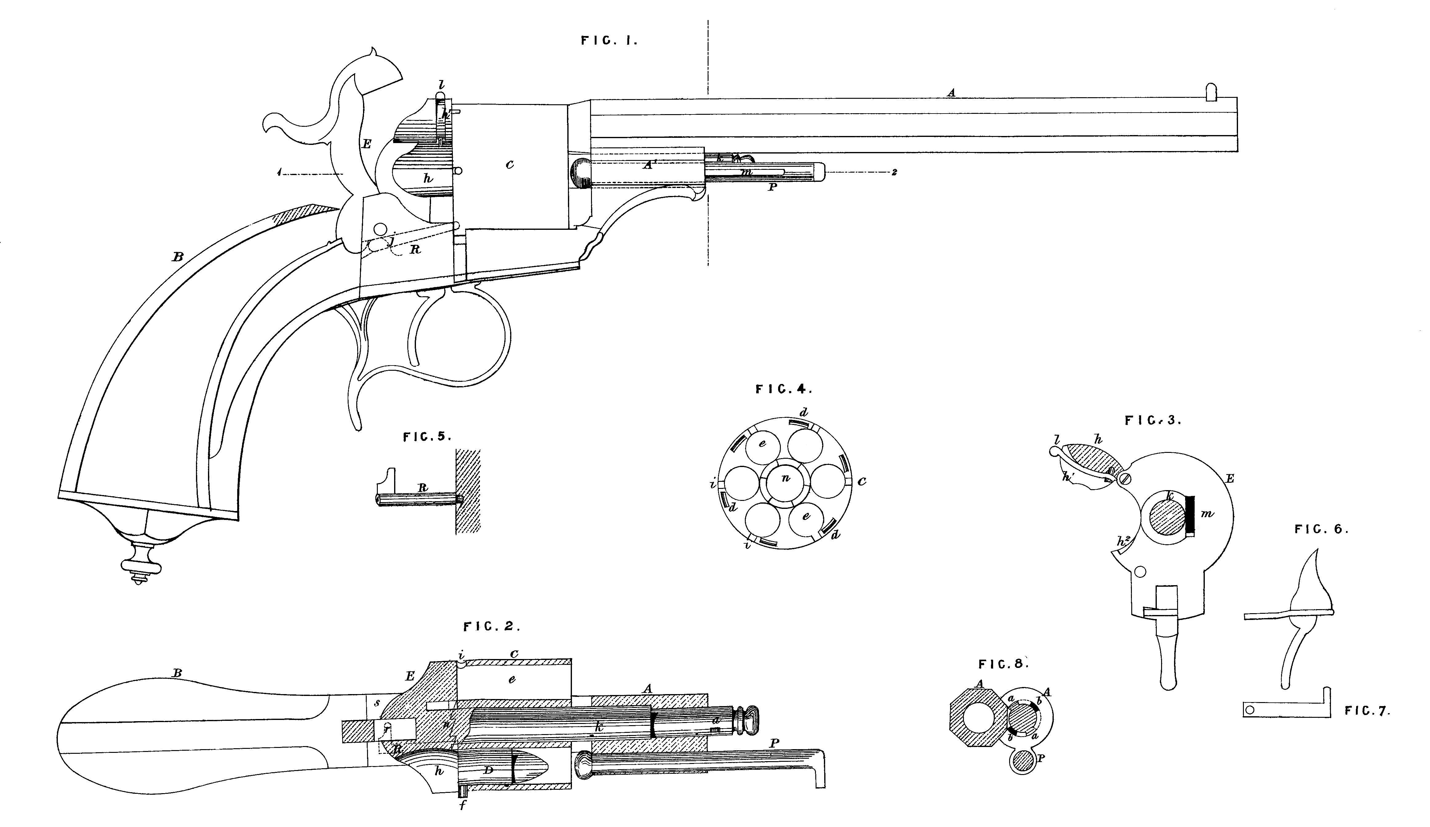
Figure 1 on the Sheet of Drawings is a side elevation of a ‘ revolver * pistol constructed according to this Invention; Figure 2 is a horizontal section of the pistol taken through the line 1, 2, in Figure 1\ that is to say, through the centre of the revolving cylinder; Figure 3 is a front elevation of the breech, shewing the central spindle in section; Figure 4 is a back view of the revolving cylinder, which is in this instance pierced for six charge chambers; Figure 5 is a view of the detent for holding the revolving cylinder in position; Figure 6 and 7 are details of the trigger; and Figure 8 is a transverse section through the barrel, shewing the manner of securing it upon the spindle, which passes through the revolving cylinder. The ordinary system is adhered to in the construction and arrangement of the barrel A and stock or handle B of the pistol, and the rotation of the charge cylinder C is effected by raising the hammer and by means of a catch m, (Figure 3,) which acts on a ratchet ring n, (Figure 4,) having six ratchets, so that on raising the hammer the cylinder C is each time turned to the extent of a sixth of a revolution. The cylinder is held in position after each shift by a peg R, fitted with a head r, which is acted upon by the tail of the hammer as to force the peg R into a notch d in the revolving cylinder when the hammer is raised, being again withdrawn on the descent of the hammer. An improved arrangement of trigger is used, which will be comprehended on reference to Figures 3, 6, and 7 of the Drawings. The revolving piece C is a cylinder, bored with (in this instance) six charge chambers e, which may be either cylindrical or slightly conical; the cylinder is also bored with a central hole for the passage of the spindle k, upon which it turns. Each of the charge chambers e is formed with a notch i, through which the percussion appliance / projects, this being affixed to the cartridge D. The breech piece E is hemispherical in shape, and is formed with a vertical groove at the back, in which the hammer works. A channel li is formed on one side of the breech piece for the introduction of the cartridges into the charge chambers e> as each is in succession brought opposite the channel h; a filling-up piece (h, Figure 3,) is hinged to the breech piece E, and serves to close the channel. This filling-up piece is fitted with a spring catch h\ which enters a notch h2 in the side of the channel, and keeps the filling-up piece closed, except when the spring is pressed by means of its extremity t. On one side of the main barrel A, and in a line with the channel h is a rod P, furnished with a small blade spring m, (Figure 1,) which keeps it in place; this rod serves for clearing out the charge chambers e when necessary. The spindle k which connects the stock B to the main barrel A, and also serves as an axis of revolution for the cylinder C, is formed with two projections a, (Figure 8,) so arranged as to enter grooves b in the socket A1 of the main barrel. In fixing on the barrel, the socket A1 is turned, so as to allow the projections a to enter the grooves b, and after being passed on the spindle the barrel and socket are turned back, and the projections a then prevent their being drawn off the spindle k; by means of this double bayonnette joint, the barrel A can be fixed to or detached from the stock with great facility and rapidity.
Having now described and particularly ascertained the nature of the said Invention, and the manner in which the same is or may be used or carried into effect, I would observe, in conclusion, that I do not confine or restrict myself to the precise details or arrangements which I have had occasion to describe or refer to, as many variations may be made therefrom without deviating from the principles or main features of the said Invention; but what I consider to be novel and original, and therefore claim as the Invention secured to me by the herein-before in part recited Letters Patent,—
First, the general arrangement and construction of fire-arms of the ‘ revolver * class, in the manner herein-before described.
Second, the application and use in fire-arms with revolving charge chambers of a breech piece, formed with a channel for the introduction of the charges into the chambers, such breech piece being provided with a filling-up piece to close the channel when necessary, as herein-before described.
Third, the application and use in fire-arms with revolving charge chambers and with a loading channel in the breech piece of a sliding rod, held in place by a spring, for clearing the charge chambers through the loading channel when necessary, as herein-before described.
Fourth, the application and use in fire-arms with revolving charge chambers of a pin, actuated by the hammer movement, for holding the revolving cylinder accurately in position during the discharge, as herein-before described.
Fifth, the system or mode of connecting the main barrels of revolver firearms to the spindle on which the charge chambers revolve by means of a double bayonnette joint, as herein-before described more particularly in reference to Figure 8 on the Sheet of Drawings hereunto attached.
In witness whereof, I, the said John Henry Johnson, have hereunto set my hand and seal, the Twenty-third day of October, in the year of our Lord One thousand eight hundred and fifty-four.
J. HENRY JOHNSON, (l.s.)