
Britain 2127
Single action revolver
LETTERS PATENT to Philip Webley, of Birmingham, in the County of Warwick, Manufacturer, for the Invention of 4i Improvements in Repeating Pi3tol3 and other Fire-arms.”
Sealed the 11th March 1854, and dated the 14th September 1853.
PROVISIONAL SPECIFICATION loft by the said Philip Webley at the Office of the Commissioners of Patents, with his Petition, on the 14th September 1853.
I, Philip Webley, of Birmingham, in the County of Warwick, Manufacturer, do hereby declare the nature of the said Invention for “ Improvements in Repeating Pistols and other Fire-arms ” to be as follows:—
The improvements consist, first, in forming the driver by which the rotation of the barrel is effected (in rotating chamber fire-arms) in one piece with the stop, which prevents the rotating chamber barrel moving too far when bringing a fresh charge chamber into position, by which simplicity of parts is effected; and, secondly, to means for insuring close contact between the inner end of the stationary barrel each charge chamber at firing, or when the hammer is against the nipple, whilst, when the hammer is withdrawn, the rotating barrel containing the charges is free of that end of the tixed barrel in rotating chamber fire-arms arranged for central fire, and this part of the Invention only applies to such arrangement of rotating chamber fire-arms.
The outer end of each charge chamber next the fixed barrel is opened or dished to receive the conical end of the fixed barrel; a sliding piece capable of acting against the rotating barrel, and placed below its axis, is acted upon by the breast of the hammer when the hammer is against the nipple to press the rotating barrel, and insure close contact between a charge chamber and the fixed barrel. When the hammer is withdrawn a spring removes the chamber from the end of the fixed barrel.
SPECIFICATION in pursuance of the conditions of the Letters Patent, filed by the said Philip Webley in the Great Seal Patent Office on the 14th March 1854.
TO ALL TO WHOM THESE PRESENTS SHALL COME, I,
Philip Webley, of Birmingham, in the County of Warwick, Manufacturer, send greeting.
WHEREAS Her most Excellent Majesty Queen Victoria, by Her Letters Patent, bearing date the Fourteenth day of September, in the year of our Lord One thousand eight hundred and fifty-three, in the seventeenth year of Her reign, did, for Herself, Her heirs and successors, give and grant unto me, the said Philip Webley, Her special licence that I, the said Philip Webley, my executors, administrators, and assigns, or such others as I, the said Philip Webley, my executors, administrators, and assigns, should at any time agree with, and no others, from time to time and at all times thereafter during the term therein expressed, should and lawfully might make, use, exercise, and vend, within the United Kingdom of Great Britain and Ireland, the Channel Islands, and Isle of Man, an Invention for “ Improvements in Repeating Pistols and other Fire-arms,” upon the condition (amongst others) that I, the said Philip Webley, by an instrument in writing under my hand and seal, should particularly describe and ascertain the nature of the said Invention, and in what manner the same was to be performed, and cause the same to be filed in the Great Seal Patent Office within six calendar months next and immediately after the date of the said Letters Patent.
NOW KNOW YE, that I, the said Philip Webley, do hereby declare the nature of the said Invention, and in what manner the same is to be performed, to be particularly described and ascertained in and by the following statement thereof (that is to say):
The improvements consist, first, in forming the driver by which the rotation of the barrel is effected (in rotating chamber fire-arms) in one piece with the stop, which prevents the rotating chamber barrel moving too far when bringing a fresh charge chamber into position, by which simplicity of parts is effected; and, secondly, to means for insuring close contact between the inner end of the stationary barrel and each charge chamber at firing, or when the hammer is against the nipple, whilst, when the hammer is withdrawn, the rotating barrel containing the charges is free of that end of the fixed barrel in rotating chamber fire-arms arranged for central fire, and this part of the Invention only applies to such arrangement of rotating chamber fire-arms. But that the Invention may be fully understood I will proceed to explain the Drawings annexed, in each of the Figures of which the same letters indicate like parts wherever they occur.
Description of the Drawing.
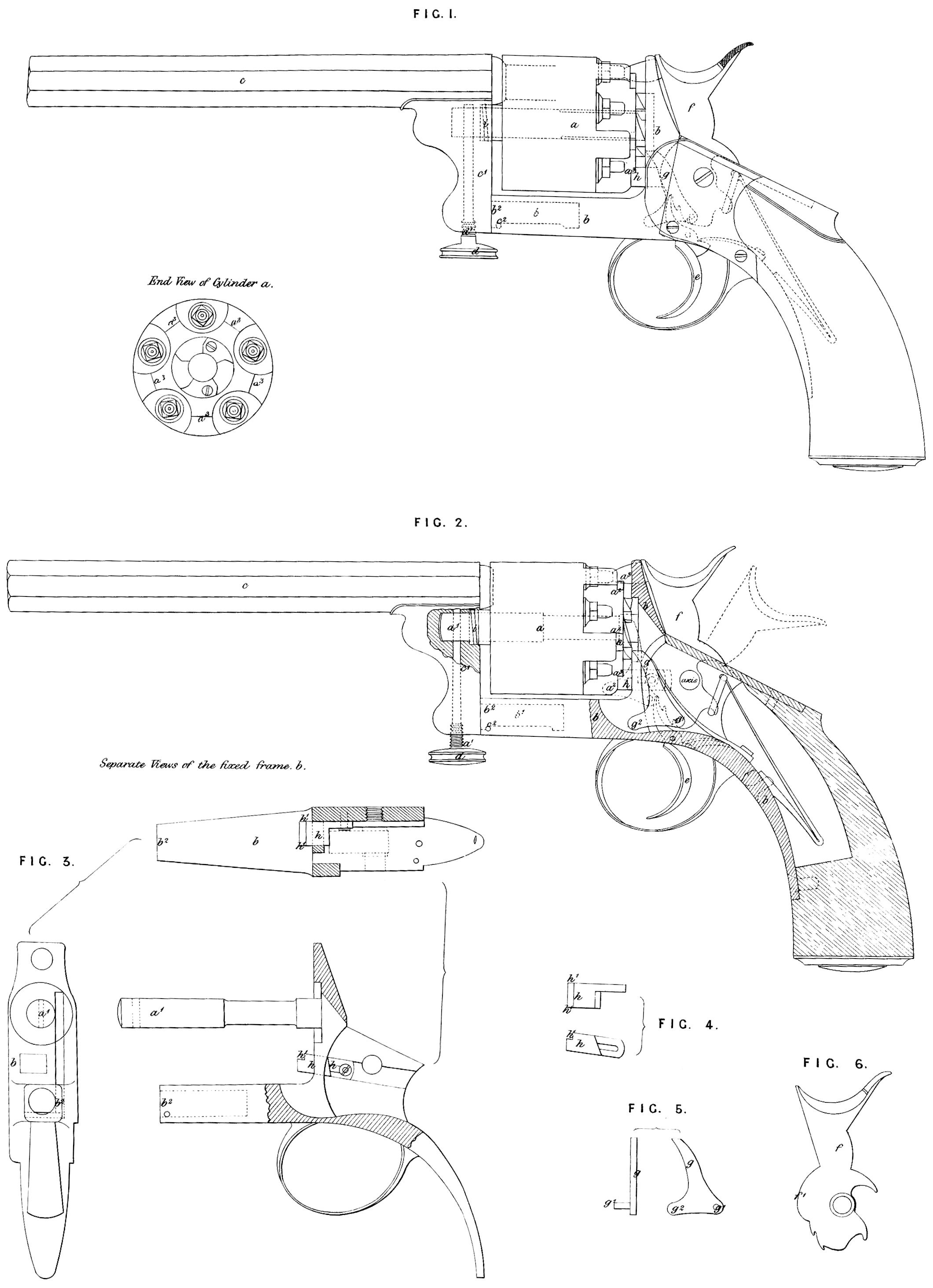
Figure 1, shows a side view of a pistol with the parts arranged according to my present improvements; Figure 2, shows a similar view, but partly in section; Figures 3, 4, 5, and 6, show some of the parts separately; and I would here state that I have thought it sufficient to show my improvements applied to a pistol only, as a workman accustomed to the manufacture of this description of fire-arms will readily make those variations in form consequent upon their adaptation to other form of rotating chamber fire-arms, a, is the rotating cylinder containing the separate charge chambers; 6, is the fixed metal part of the framing, which at its outer end b2, supports the barrel c, by means of the projecting arm c\ with a capability for the barrel c, turning upon the end b’\ of the frame b, when it is required to remove or replace a cylinder a, according to improvements for which I obtained Her Majesty’s Letters Patent, bearing date on or about the Fourth day of February, One thousand eight hundred and fifty-three; but the pin b\ upon which the parts turn, in place of being affixed to the part b, and turning in a hole provided for the purpose in the stem c\ as was described in the Specification of the Patent before referred to, is in the present case affixed to the stem c\ and passes into a socket formed in the framing b, as shown, but it is governed in its movement by a pin c2, in like manner to what was there described. The pin d, for holding the barrel c, up to the cylinder a, passes into the end of the axis a\ of the cylinder a, and it is formed at its lower part with a male screw d\ by turning which into a corresponding female screw formed in the lower part of the stem c\ the bolt d, is prevented getting loose from the pin a\ All which, however, being only a modification of that shown and described in my said former Specification, forms no part of the present improvements and are only referred to in order to explain the variation in the arrangement of the parts as shewn by the present Drawing, c, is the trigger; /, is the hammer; and g, the driver for causing the partial or step by step rotation of the cylinder a, in order to bring fresh charge chambers successively in a line with the barrel c. This driver g, turns by a pin joint g\ at its lower end upon the hammer /, and it is formed with a projection g\ which, when the driver is acting to turn the cylinder for the bringing up of a fresh charge chamber, comes into position to act against one of the side pieces a2, of the cylinder a, to prevent the cylinder turning too far, and it is the forming such driver and stop (of fire-arms of the kind described) in one piece which constitutes the first part of my Invention. In order to insure close contact between the end of the barrel r, and each charge chamber in the cylinder a, when firing, or when the hammer is against the nipple, the breast/1, of the hammer/, acts by the sliding stump k, to force the cylinder a, into close contact with the inner end of the barrel c, to effect such contact. But when in “ cocking ” the hammer head is withdrawn from the nipple, the breast f\ is also withdrawn from pressing the stump h, upon the cylinder; a coiled spring ?, then frees the cylinder a, from the inner end of the barrel c, in order that the next partial rotation may be readily effected. The outer end of each of the chambers in the cylinder a, is opened or dished to receive the conical end of the fixed barrel c. The stump k, is formed with a straight surface h\ to h\ capable of fitting against each of the corresponding surfaces a\ of the cylinder a, to assist in holding the cylinder a, steadily when firing.
Having thus described the nature of my said Invention, I would have it understood that I do not confine myself to the precise details herein showrn and described, so long as the peculiar character of either part of my Invention be retained. But what I claim is,—
First, the forming the driver used to cause the rotatory movement of the charge chamber or cylinder of repeating pistols and other fire-arms having a fixed barrel in one piece with the stop, by which the chamber at each movement is prevented moving too far; and,
Secondly, I claim the so arranging parts of repeating pistols and other fire-arms arranged for central fire that the rotating charge cylinder may at firing, or when the hammer is against the nipple, be forced into close contact with the inner end of the stationary barrel by the action of the hammer, and when the hammer is withdrawn from the nipple the cylinder may be relieved by spring pressure from contact with the stationary barrel, so as to bo free to revolve.
In witness whereof, I, the said Philip Webley, have hereunto set my hand and seal, this Fourteenth day of March, in the year of our Lord One thousand eight hundred and fifty-four.
PHILIP WEBLEY. (l.s.)
Witness, *
William Brookes,
Patent Agent,
73, Chancery Lane.