
Britain 277
A.D. 1878, 22nd January. № 277
Revolving Fire-arms.
LETTERS PATENT to Joseph Merwin, Milan Hulbert, and William Augustus Hulbert, Merchants, of the City of Brooklyn, in the County of Kings, and State of New York, United States of America, for the Invention of “Improvements in Revolving Fire-arms.”
Sealed the 8th March 1878, and dated the 22nd January 1878.
COMPLETE SPECIFICATION filed by the said Joseph Merwin, Milan Hulbert, and William Augustus Hulbert at the Office of the Commissioners of Patents on the 22nd January 1878.
Joseph Merwin, Milan Hulbert, and William Augustus, Merchants, Merchants, of the City of Brooklyn, in the County of Kings, and State of New York, United States of America. “Improvements in Revolving Fire-arms.”
This Invention relates to revolving fire-arms designed to use metallic-cased cartridges; and it consists in the construction and combination of parts, as will be herein-after more fully set forth and pointed out in the claims.
In order to enable others skilled in the art to which this Invention appertains to make and use the same, its construction and operation will now be described, reference being had to the accompanying Drawing, and to the letters of reference marked thereon, which forms s part of this Specification, and in which,—
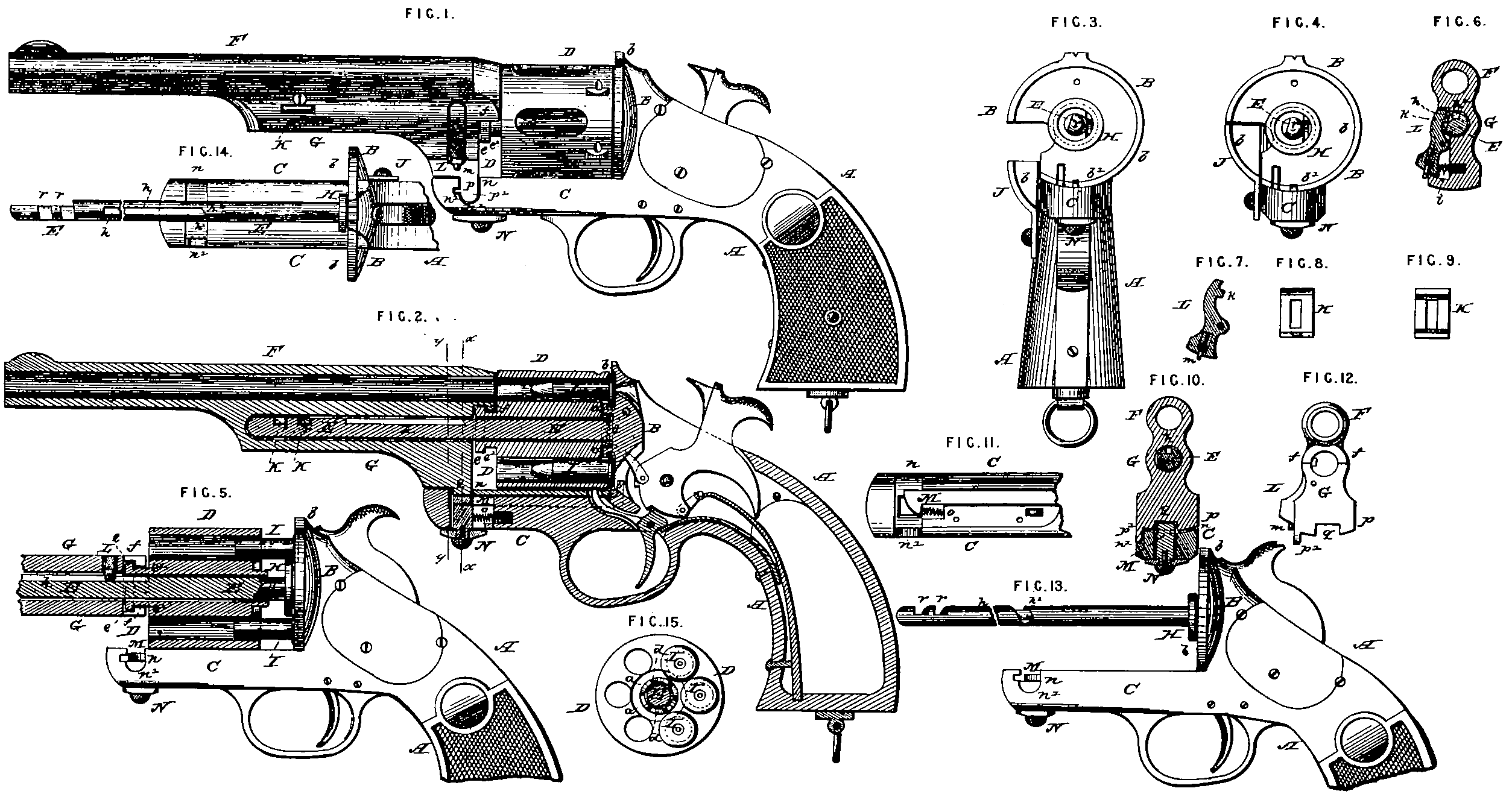
Figure 1 is a side elevation of the improved revolving fire-arm; Figure 2 is a longitudinal section of the same.
Figure 8 is a front view of the recoil shield with the gate dropped down; Figure 4 is a similar view with the gate closed.
Figure 6 is an enlarged longitudinal section of the cylinder and recoil shield.
Figure 8 is a cross section on the line y, y, Figure 2.
Figure 7 is a face view of the spring stop, by which the barrel in sliding on the centre pin is stopped at a given point.
Figures 8 and 9 are opposite face views of s key employed in locking the barrel on the centre pin.
Figure 10 is a cross section of the pistol on the line a, a, Figure 2.
Figure 11 is an upper face view of the strap of the frame.
Figure 12 is a rear end view of the barrel and bracket.
Figure 13 is a side view of the fire-arm with the barrel and cylinder removed.
Figure 14 is a plan view of the outer end of the centre pin.
Figure 15 is a rear end view of the cylinder detached.
A represents the frame with the recoil shield B and the strap C, the latter extending longitudinaBy under and beyond the front end of the cylinder; D is the many-chambered revolving cylinder rotating upon the centre pin E, which projects from the frame in the centre of the recoil shield; F is the barrel, with bracket G underneath.
The mechanism of this pistol (shown in the Drawing), so far as relates to the hammer, trigger, main and sear springs, and the device for locking the cylinder rotarily, does not difFer essentially from that now in, use; 5 particular description of the same is therefore unnecessary.
The recoil shield B is formed or provided at H with a projecting collar or short tube, surrounding and concentric with the base of the centre pin E, in the outer circumference or periphery of which collar is turned out an annular groove or channel, as shown, close to the forward face of the recoil shield, so as to form a shoulder, past which project (toward the centre pin) the Ranges of the cartridge cases or shells I. In the rear end. of the cylinder D is cut or turned out an annular recess or groove a, which it wiB be observed is concentric with the central hole of said cylinder, and with its series of cartridge chambers, and into this recess a fits the collar or ring H of the recoil shield, in the manner shown. From this Construction and combination of parts it follows that when the cylinder D is in place, and its chambers filled or loaded with cartridges I, the flanges of the latter will at a point nearest the base, or centre pin, or centre of rotation of said cylinder, project inwardly past or in rear of the collar H, and into the channel or groove formed therein. This groove being a very little wider than the flanges of the cartridges are thick; the part of said Ranges which project into said channel can move round freely therein without hindrance or friction whenever the cylinder is rotated on the centre pin; but whenever the cylinder is pulled off of the centre pin, or moved longitudinally thereon, the said projecting portions of the flanges of the cartridges will hang in said channel and hold on against the shoulder or rear edge of the collar, and be detained rearward while the cylinder is being moved forward, and thus the cartridge shells will be efFectually extracted or withdrawn from the chambers of the cylinder whenever the latter is moved longitudinally forward on the centre pin. The groove a in the rear end of the cylinder does not practically weaken the walls of the chambers in the cylinder, because said groove is always completely filled or blocked up by the ring extractor H when the chambers are being discharged of their contents.
The ring extractor H may be either formed with the recoil shield in one piece, or it may be made separate, and permanently secured to the recoil shield or to the centre pin.
The recoil shield B is made solid, and formed with a drop gate J for opening and closing the passage or groove through which the cartridges are inserted in the cylinder. When this gate J is closed the recoil shield forms a complete circular breech for the fire-arm. With the annular or ring extractor H, as above, described, for simultaneously extracting all the shells, it often happens that the heads or flanges of the cartridges extracted entirely from the cylinder. The cause hereof is that the heads of the cartridges are unconfined at a point opposite the extractor, and hence there is room for them to move laterally. To obviate this difficulty a forwardly projecting rim or flange b is formed around the entire outer circumference of the recoil shield, including the drop gate J, which rim or flange confines the heads of the cartridge shells at points diametrically opposite to the points where they are held by the extractor, and thus prevents them from moving laterally or dropping away from the extractor, and hence insures the complete extraction of them from the cylinder.
It will be noticed that the recoil shield B is perfectly rind, and forms a part of the frame A, of which C is the projecting part or strap below the cylinder. The rim or flange b around the recoil shield is extended across the top of this strap C, as shown at b¹ in Figure 4, so as to form s continuous guard around all the cartridge heads in the cylinder.
In some cases the extractor H might be formed on the recoil shield so as to grasp the cartridge heads at their outer edges, and in such cases the confining rim or lunge b should be formed on the axial or centre pin.
The inside lunge formed at the rear end of the cylinder D around the central hole by the annular recess or groove a is projected a trifle beyond the end of the cylinder and forms the ratchet d for rotating the cylinder, said ratchet being thus formed on the cylinder and not ob the extractor, as is usually the case.
After the loads or cartridges have been fired off the expansion of the shells often causes them to stick in the chambers, so that it is difficult to move the cylinder longitudinally forward from the recoil shield, as the heads of the shells are held by the extractor H. To obviate this difficulty the parts are so constructed that by rotating the barrel F the cylinder is at the same time moved forward on the axial pin E, thereby forcibly starting the same away from the shells which are held in the extractor. The mechanical means shown in the Drawing for accomplishing this object are as follows:— On the forward face of the cylinder D is a projecting boss e, having an annular recess e¹ next to the face of the cylinder; and upon the rear end of the barrel is formed a semicircular collar or roof-like cover f, recessed to receive the projecting rim of the boss e. When the barrel and cylinder sre in position on the centre pin this boss and collar form a lock by which the cylinder is drawn forward on the pin with the barrel, and also forms a gas check. The bracket G is made in one piece solid with the barrel, and is bored nearly through longitudinally to receive the cylindrical centre pin E, Near its font end it has a suitable slot or opening to receive the locking key bolt K L is s retaining stop, pivoted in an opening in the side near the rear end of the bracket, and pressed into engagement with a transverse notch or groove h¹ in the centre pin by a spring f, The said transverse groove V opens into a longitudinal groove h, thus permitting the bracket and barrel to be drawn off from the centre pin until the nose h of the catch L in traversing the said groove h is stopped against the end thereof; then if it is desired to remove the barrel entirely from the centre pin it, may be done by pressing upon the lower end of the catch L, thereby lifting its nose out of the groove. The lower end of the catch L is provided with a small spring stop m which prevents said catch from being accidentally pressed down, and thus disengaging the barrel. By however pressing in said spring stop the catch can be manipulated, as described.
At the junction of the two grooves h and h¹ in the centre pin E is an incline h², as shown in Figures 13 and 14.
Near the fore end of the strap C of the frame is a slot n across the same to receive a lip or projection p formed on the face of the base of the bracket G. The projection p is formed with s lip p¹ to enter a notch n¹ in the side of the strap to prevent the bracket from swinging beyond its proper point. In a longitudinal groove in the upper face of said strap is a sliding catch M, the beveled end of which is pressed forward into the slot n by spring o. When the bracket is swung to its place over the strap the projection p presses back the catch M against the spring o until the bracket reaches its position, and the lip p¹ stops in the notch n¹, when the said catch, under the stress of said spring o, slides forward into a notch f cut across the projection p, and thereby the bracket is securely locked in position. N is a finger piece, the stem of which is connected to the catch M through a slot in the strap, whereby the said catch may be withdrawn and the bracket unlocked from the strap. The barrel and bracket can then be turned one-fourth of a revolution on the pin E, so as to entirely withdraw the bottom projection p from the slot or groove n, and until the end of the atop L enters the slot h on the axial pin. As soon as the projection p has cleared the slot n the nose k on the stop L strikes the incline h², so that simultaneous with the latter portion of the rotating movement of the barrel, the barrel and cylinder (they being locked together as above described) will be moved longitudinally on the axial pin E by the nose h riding along the incline h² to enter the longitudinal groove h. Thus the cylinder is forcibly started from the cartridge shells, which are held by the extractor on the recoil shield, and loosened before their final extraction.
It, is evident that various other mechanical means may be employed for moving the cylinder forward on its axial pin simultaneous with, and by the action of, the barrel in being rotated; and the same result may be accomplished in fire-arms having a strap extending above the cylinder as well as below the same. On the end of the centre pin E are fenced key bits r, r, the portion forming the bolts being flattened by the cutting away of about one-half of its diameter, so that, it may pass under the key bolt K, and then, by being turned a quarter around, locked into said key bolt
By the extension of the centre pin along under the barrel within the drilled-out solid bracket beneath it, when the parts are brought in position for firing, and the bracket foot or projection swung within the slot in the lower strap of the frame, all the parts are firmly locked together and require no additional aid of key bits, bolts or catch devices (to resist the recoil of the discharge), either upon the centre pin or to act thereupon.
It is evident that when the barrel with its bracket and the cylinder attached are placed upon the extended centre pin, and the foot of the bracket in position, said parts cannot be separated unless by transversely breaking the centre pin, or turning the bracket foot out away from the slotted strap, or breaking the strap, which cannot be done by any usual revolver cartridge charge, as the lines of resistance to separate the parts are in the angles of an arch. This strong and simple construction, whereby the centre pin not only forms the base pin for sliding forward the barrel and the cylinder but also forms the axial pin on which the barrel is rotated upon its centre, so as to allow the foot of its bracket to swing into or pass out of slot cut in the frame strap constitutes an important part of the Invention.
Much difficulty has been experienced in preventing the gases from the discharge passing into the assembled parts lying in front of the cylinder, and particularly so ns to the centre pin, when said pin is extended so as to be used as a base pin for sliding forward the barrel and cylinder, as well as for a central axial pin for rotating the same. To prevent this difficulty the barrel is constructed at its rear end with the roof-like cover f, that extends partially down upon the bracket rear, and sufficiently surrounds the centre pin at that point to deflect and throw off the gases from the parts described, and at the same time admit the rim of the covering boss e on the front of the cylinder to take in the semicircular recess formed in the under part of the said deflector; thus it acts as a clutch for carrying forward the cylinder with the barrel for extracting the cartridge shells.
The key bolt K forms an additional lock when the parts are in position for firing. The use of this key bolt separate from the barrel is recommended; but, if preferred, one or more projections map be formed on the under side of the barrel, corresponding in form and position to the body of the bolt when in place, the nose at the front end of the bracket being cut away for the purpose, and the space ‘thereby exposed capped by a separate piece screwed on.
Having thus fully described the Invention, what is claimed as new and desired to be secured by Letters Patent is,—
1st. The combination with a removable cylinder having a suitable recess or groove for its reception of a fixed collar or ring-like extractor, substantially as set forth.
2nd. In a revolving fire-arm a rigid recoil shield provided with an annular ring extractor and a drop gate for loading through the recoil shield on to the extractor, substantially as herein set forth.
3rd. In a revolving fire-arm the combination of a stationary ring extractor and a rotating and sliding cylinder having the ratchet formed thereon, substantially ns set forth.
4th. In a revolving fire-arm a rigid recoil shield B provided with a forwardly-projecting rim or flange b around its entire circumference, and an annular extractor, substantially as and for the purposes herein set forth.
6th. The frame strap C provided with the flange or shoulder b¹ to forms continuation of the rim b surrounding the recoil shield, for the purposes herein sot forth,
6th. In a revolving Fire-arm the combination of a barrel, a cylinder, a forwardly-projecting combined slide rod and centre pin, and an extractor, substantially as shown, whereby a partial rotation of the barrel on said centre pin permits the sliding forward longitudinally of the barrel and cylinder on said combined slide rod and centre pin, and extracts the cartridge shells, as specified.
7th. The combination in s revolving fir-arm of the centre pin E, provided with the slots h, h¹, and incline h², the spring catch L, and the bracket G, as and for the purpose specified.
8th. In a revolving fire-arm a longitudinally sliding barrel, a cylinder, and a frame strap, in combination with an extended slide rod centre pin, as and for the purpose specified.
9th. The combination in a revolving fire-arm of the bracket G and the barrel E with the centre pin E, provided with the flattened key bits r, r, and the key bolt K, as and for the purpose specified.
10th. In s revolving fire-arm the combination of the barrel and cylinder with a centre pin, said pin provided with incline, transverse, and longitudinal slots, the barrel being provided with n, stop or projection to engage with said slots, for the purpose herein set forth.
11th. In a revolving fire-arm the combination of a frame strap or straps provided with a slot or groove, the cylinder and barrel provided with a projection to engage in said slot or groove, for the purpose herein specified.
12th. The combination of the central pin E having slots h, h¹, and incline h², the cylinder D, frame strap C with groove et, and spring bolt M, the bracket G with notched projection p, and the spring slot L, all constructed substantially as and for the purposes herein set forth.
13th. The spring stop m, arranged in the end of the retaining stop or catch L, for the purposes herein set forth.
In testimony whereof, wo have hereunto set our hands and seals, this 2nd day of January, in the year of our Lord 1878, at the City of New York.
JOSEPH MERWIN. (L.S.)
MILAN HULBERT. (L.S.)
WILLIAM AUGUSTUS HULBERT. (L.S.)
Witnesses,
John H Howell.
Henry Berkel.