
Britain 922
A.D. 1878, 7th March, № 922.
Repeating Fire-arms.
LETTERS PATENT to John Henry Johnson, of 47, Lincoln’s Inn Fields, in the County of Middlesex, Gentleman, for the Invention of “Improvements in Repeating Fire-arms.” A communication from abroad by Paul Mauser, of Oberndorf, Wurtemberg, in the Empire of Germany, Gunmaker.
Sealed the 18th August 1878, and dated the 7th March 1878.
PROVISIONAL SPECIFICATION left by the said John Henry Johnson at the Office of the Commissioners of Patents on the 7th March 1878.
John Henry Johnson, of 47, Lincoln’s Inn Fields, in the County of Middlesex, Gentleman. “Improvements in Repeating Fire-arms.” A communication from abroad by Paul Nasser, of Obeindorf, Wurtcmberg, in the Empire of Germany, Gunmaker.
This Invention relates in that class of revolvers or repeating fire-arms in which the rotation of the chambers is effected by the act of drawing back the hammer or cocking the gun, and it consists of the following improvements in the details, and in the general arrangements and combinations of the parts of revolvers of this description whereby their construction is simplified, and increased safety in their operation, is obtained.
1st. A revolving cylinder is employed having inclined and parallel grooves cut or formed in its circumference, in which works a pin or pawl for actuating the cylinder, the arrangement being such that the cylinder is caused to rotate when the said pin or pawl is engaged in the inclined grooves and is maintained stationary. when it is engaged in the parallel grooves The pin or pawl is arranged in connection with the hammer mechanism as herein-after described.
2nd. The extractor is provided with cam-shaped surfaces and notches at the rear end, with which engages the pin of s safety slide so as to prevent the binder part of the extractor from rotating, and cause the fore part to ride over the cam when the cylinder is caused to rotate in one direction and project the shells out of the chambers.
3rd. The box or case of the revolver is fitted with a safety slide (herein-before referred to) performing 3 functions, vist:—
a. Holding together the two parts of which the ease of the revolver is constructed, the said two constituent parts of the case being hinged together. The case is opened for the discharge of the cartridge case by moving the slide, whereby it is released from a nose catch.
b. Preventing the cocking of the hammer when the two parts of the case are not completely closed together, the slide intercepting in this condition of the parts a sliding bolt which actuates the hammer.
c. Preventing the rear part of the extractor from rotating as before mentioned.
4th. The sliding bolt is moved by the hammer in one direction when the gun is cocked, and returns under the action of a spiral spring actuating the hammer when the trigger is released. The bolt is provided with a socket having a hook for a purpose herein-after explained, and also with notches for the engagement of the trigger, and is further fitted with a spring pawl which engages in the grooves of the cylinder as before mentioned for the purpose of actuating the same.
5th. The hammer is bifurcated, the two branches of the fork embracing the sliding bolt.
6th. The trigger-guard plate is provided with two hooks and a projection by which it is fastened to the case, tbc parts of the lock being held together by one of the hooks engaging with a catch formed in a socket in which the sliding bolt is fitted.
SPECIFICATION in pursuance of the conditions of the Letters Patent filed by the said John Henry Johnson in the Great Seal Patent Office on the 18th August 1878.
John Henry Johnson, of 47, Lincoln’s Inn Fields, in the County of Middlesex, Gentleman. “Improvements in Repeating Fire-arms.” A communication from abroad by Paul Mauser, of Oberndorf, Wurtemberg, in the Empire of Germany, Gunmaker.
The said Invention relates to s revolver or repeating pistol of entirely new construction, differing materially from the systems hitherto adopted. The rotation of the chambers in this revolver is effected by the act of cocking or drawing back the bummer, as in what are known se the new American revolvers. The hammer is cocked by the thumb before each shot. This has the effect of reducing the speed of firing to a certain extent, which however is compensated for by the much greater security of the charge.
The following are the principal advantages of the new revolver.
The pawl or piece for actuating the rotating cylinder containing the chambers does not engage with the rear surface of the said cylinder as in the case of American revolvers, but with the circumference of the same. The arm of the working lever is thereby considerably lengthened, and the cocking of the hammer facilitated. Greater safety is obtained by the arrangement, as well se the advantage of preventing the gas resulting from the combustion of the powder from penetrating into the box or case of the lock as the mechanism for actuating the cylinder is removed from the rear of the cylinder to the circumference, and the recoil plate contains no perforations communicating wish the interior of the lock.
This revolver is also characterised by the great simplicity of its mechanism; it is constructed entirely with 33 pieces only, whilst the American revolvers sometimes contain 56. It consequently admits of being taken to pieces with great facility.
For the purpose of cleaning the revolver a single screw only requires to be unscrewed; the whole of the parts may be then taken out by hand and cleaned and lubricated.
A further peculiarity consists in the novel construct, ion of the extractor as herein-after described.
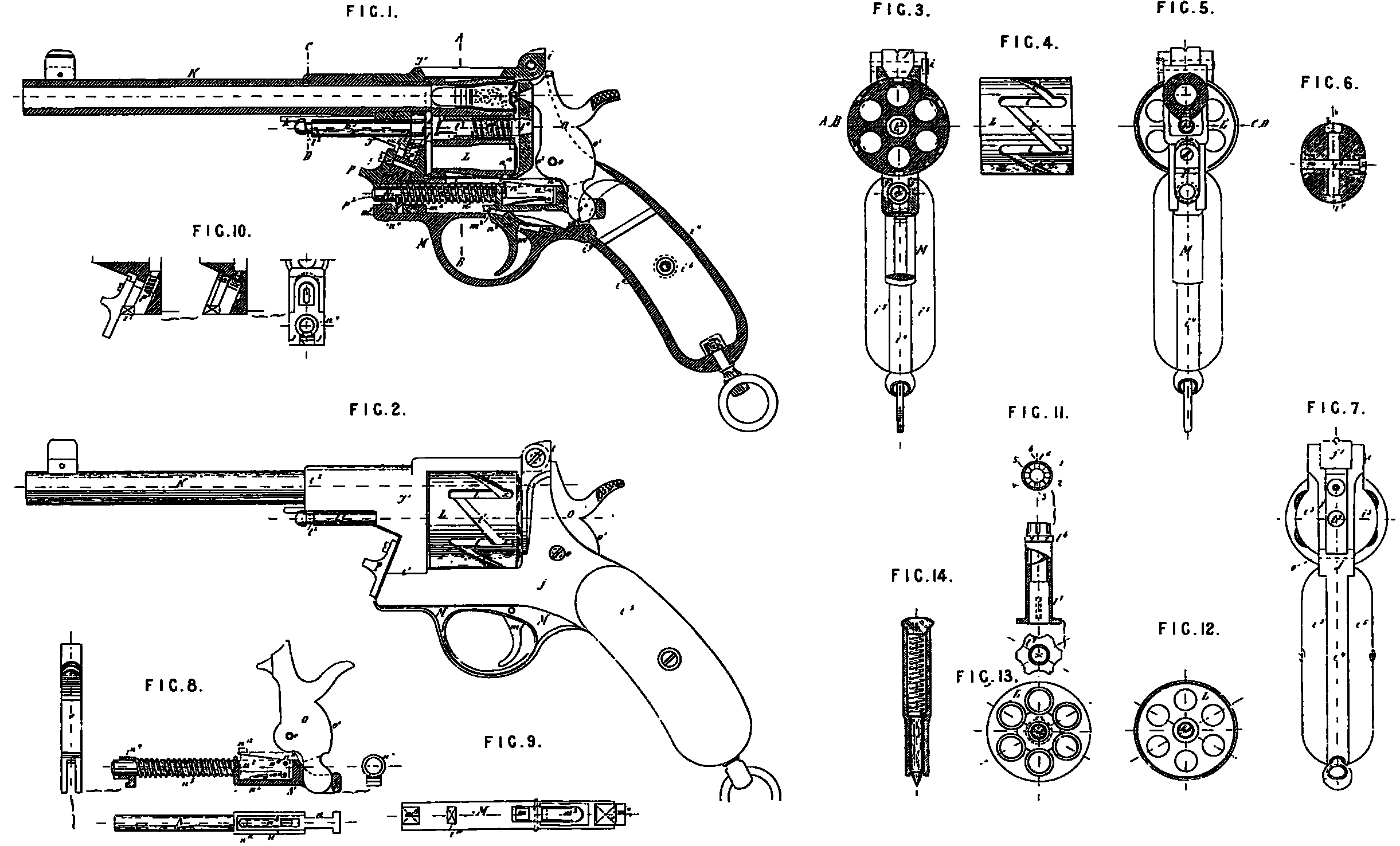
And in order that the said Invention may be fully understood, I shall now proceed more particularly to describe the same, end for that purpose shall refer to the several Figures on the annexed Sheet of Drawings, the same letters of reference indicating corresponding parts in all the Figures.
Figure 1 of the accompanying Drawing represents a longitudinal section through the centre of the revolver, showing the whole of the internal mechanism;
Figure 2 is a side elevation of the same.
Figure 8 is s transverse section taken along the line A, B, Figure 1.
Figure 4 is a side elevation of the cylinder chewing more particularly the grooves cut in its circumference in which the pawl or piece works which causes the rotation of the said cylinder.
Figure 5 is a transverse section taken along the line C, D, Figure 1, the view being taken from the front.
Figure 6 is s transverse section of the stock showing tLe attachment of the wood.
Figure 7 is s view of the revolver seen from behind.
Figure 8 is a detail chewing the hammer, and the spring, and sliding bolt by which it is actuated.
Figure 9 is a plan of the trigger guard plate.
Figure 10 represents details of the safety slide herein-after referred to.
Figure 11 shows three detail views of the extractor.
Figure 13 is a view of the fore end of the revolving cylinder, Figure 13 is a view of the rear end of the same.
Figure 14 represents a sectional elevation of a key or instrument for releasing the trigger guard plate when it is required to take the arm to pieces.
The principal parts are marked in the Drawing with capital letters, and the smaller parts of which the principal parts are composed are marked with the corresponding small letters, with the addition, where required, of numbers.
J, J¹, is the body, frame or case of the revolver. It consists of two parts, J, J¹, which are connected together by a hinge i, and open at i¹; K is the barrel; L, the revolving cylinder; M, the trigger guard plate; N, the sliding bolt acting on the 10 hammer; O, the hammer; P, the safety slide.
The body or case J; J¹, is of iron or steel, with flat sides, and hollowed out internally to provide room for the look. The frame part i² is somewhat thickened and provided with an internal screw for the reception of the barrel. Behind the revolving cylinder the body is expanded in the form of a circular recoil plate i³; the rear part is completely hollowed out, and only consists of a thin band i⁴ (Figures 1 and 6), which is imbedded in the wooden stock i⁵; s single screw i⁶ is sufficient to secure the wooden stock to the metal band i⁴. The body or case J¹ is cut sway at the upper part over the revolving cylinder in such a manner as to admit as little dirt as possible. Any gas which may be present is thus enabled to escape readily. The hack sight is formed upon the hinge.
A recess is provided in the back of the body for the reception of the hammer, which fits closely therein, and is formed with two curves o¹, o², which fit as closely as possible against the aides of the recess, and being struck front a common centre o, serve to exclude dirt at this part. The hollow of the body is closed underneath by the trigger guard plate M. Underneath the revolving cylinder a us&vow opening or slit only is formed in the body or case for the passage of the pin for effecting the rotary motion of the cylinder, in which opening or slit the said pin travels to and fro. The cylinder itself serves to close this opening and prevent any dirt from entering at this point.
At the front part where the end of the sliding bolt for actuating the hammer is passed through the body or case, the opening is closed by the bolt itself, and s collar or socket n⁴, which surrounds it.
The trigger m entirely fills the aperature in the trigger guard plate, through which it communicates with the inner part pf the lock, its detent m²; with the part of the sliding bolt N, in which the half cock and full cock notches n⁶ and n⁷’ respectively are formed, closes the front part of the aperture, the rear part m¹ of the same is closed by the trigger spring m³.
In order to admit of the extraction of the exploded cartridge cases the body or case of the arm is so constructed and arranged as to be readily opened by pushing up the safety slide P in the direction of the arrow, whereby the nose i⁷ is liberated from the catch p. The position of the hinge with relation to this catch is such, as shewn in Figure 1, Chat this mode of fastening is perfectly secure.
The barrel K, which may be constructed in any usual or suitable manner, is screwed into J¹.
The revolving cylinder L is of peculiar construction. It contains, or may contain, six chambers ss usual, and turns upon a centre pin or axis l³, one end of which is supported in shearing i⁸, formed in tbc body J¹, and the other end, which is of conical shape, fits exactly into a hole bored for its reception in the centre of the recoil plate Cs. The rear part of the centre pin is of conical shape to facilitate its passing in and out of its bearing in the recoil plate on opening or closing the case.
The front end of the centre pin is provided with s small annular groove l³, which engages with a projection formed on a spring k, this spring being located as (shewn in the section, Figure 5,) in a groove formed under the barrel, and having its rear end bent up at right angles and held between a shoulder on the barrel and the case J¹.
A steel bush, consisting of two parts l⁶, l⁷, termed the extractor, is passed over the centre pin l³. The said bush is shown separately in Figure 11. The conical end l⁸ fits into a conical hole bored in the case; the space between the case and the cylinder is occupied by a small filling piece or washer 7. In the said conical part there are formed six notches marked respectively 1, 2, 3, 4, 6, and 6, the object of which is herein-after explained.
The two ends of the two tubular pieces l⁶ and l⁷ which are in contact and constitute tbc extractor form spiral cams which prevent the rotation of the part l⁷ in one direction when the l⁶ is stationary, whilst the rotation of the said part
7 in the other direction can only take place by riding over the cams. The part l⁷ is provided with a flange, which is sunk in a corresponding recess formed in the end of the revolving cylinder, so that its outer surface is flush with the rear end of the mid cylinder. The flange is sufficiently broad to extended as far as the cartridge chambers, and is them cut away in six places corresponding with the six chamber; so as to fit under the flanges of the cartridges.
In order to remove the cartridge shells from the chambers by means of this extractor the case is opened by pushing up the safety slide P in the direction of tbc arrow, whereby the nose l⁷ is liberated from the catch p; at the same time however the flattened end of the pin p¹ engages with one of the notches l, 3, 3, 4, 5, and 6. The fore part l⁷ of the extractor is provided with a projection, which works in a groove formed in the revolving cylinder. When the pin p¹ is caused to enter one of the notches by pressure on the sliding piece B, the cylinder L is only capable of rotating in one direction, videlicet, in that direction in which the cam on the part l⁷ is able to ride over the cam on the part l⁶. The perpendicular ends of the cam prevent its rotation in the opposite direction. As the cylinder rotates the part l⁷ is pushed out by the action of the cams, and expels the shells of the cartridges, so that they all drop from the chambers simultaneously into the hand.
The circumference of the revolving cylinder L iv provided with grooves l, l¹, which pass round it in a six-sag direction; the grooves l are parallel with the generating line of tbc cylinder; the inclined grooves l¹ each connect one end of one of the parallel grooves l with the opposite end of the next corresponding parallel groove. The bottoms of the parallel grooves are inclined, and rise from the rear end towards the connection with the inclined groove (Figure 4). The pawl or pin for actuating the revolving cylinder works in this groove, and is pushed down it by the aid of cocking the hammer.
The pawl consists of a small tongue n⁸, which is centred on a pin n⁹, and moves in n recess formed in the eliding bolt, which actuates the hammer A. Spring n¹⁰ forces the tongue or pawl upwards in the recess, its end n¹¹ bears against the sliding bolt.
When the hammer O is cocked its bifurcated end o¹ pushes the sliding bolt N forwards. The projection n¹² on the pawl n⁸, which is forced forwards with the bolt, engages in one of the inclined grooves l¹, and as it moves forwards in a line parallel with the axis of the cylinder it causes the latter to describe a fraction of a revolution. On reaching the end of tbc inclined groove l¹ the projection n¹² enters the deep end of one of the parallel grooves k, and at the seine moment the detent m² of the trigger m engages in the pull cock notch n⁷ under the sliding bolt N. On pulling the trigger the detent m² releases the bolt N, which slips back, carrying with it, the pawl n⁸, and tbc projection n¹² slides back along one of the parallel grooves l without moving the cylinder. During this motion the projection n¹² passes from the deep end of the parallel groove l along the inclined bottom of the groove to the shallow end, where it suddenly drops into the deep end of the next inclined groove at the angle x, x, (Figures 2 and 4).
On cocking the hammer again the preceding operations are repeated, so that the revolving cylinder is again turned round one-sixth of a revolution, and another chamber brought into position for firing. On cocking the hammer the spring n⁵ is compressed. The said spring bears against the socket, or guide n⁴ (Figures 1 and 8), at one end, and against a shoulder n⁴ formed on the bolt N at the other end. The hammer fits into the recesses n, n, formed in the sides of the bolt N.
The sliding bolt N moves in a straight line in the direction of its length, being guided at the front end by the socket n⁴, and behind by the cylindrical guide n¹, Figure 3.
The half cock notch n⁶ is of such a shape that the detent of the trigger is firmly retained in it; when the bolt is drawn back the full cock notch n⁷ is cut at a more obtuse angle, so that a comparatively slight pressure of the finger on the trigger suffices to release the bolt which is impelled forwards by the action of the spring. The same movement throws the hammer forward bringing its nose suddenly into contact with the cap and explodes the cartridge.
The trigger guard plate M is connected to the under part of the case in the following manner:— A hook m⁴ embraces the angle i⁹, and a hook m⁵ at the forward end engages in a hook n⁴ formed on the socket or guide of the sliding bolt, and which is retained in position by the spring n⁵. A projection m⁶ on the plate bears against a bridge or projection i¹⁰ on the case. This simple method of fastening the trigger guard plate thus enables all screws to be dispensed with, and admits of its being unfastened by means of an instrument in the form of a hollow key (Figure 14) which is pressed in until the hook m⁵ is liberated. The trigger guard plate will then drop out, and the socket or guide will be pushed out by the spring. The screw o of the hammer may then be unscrewed and the hammer taken out. The sliding bolt N maybe then removed by pressing the projection n¹² on the pawl into the recess i¹¹, and drawing the bolt back until its front end can be passed behind and under the bridge i¹⁰, and thus enable it to be withdrawn with facility.
The trigger m is maintained in the notches by means of a trigger spring m³, which is fitted into a dovetailed recess in the trigger guard plate.
The safety slide P performs three functions; in the first pLsce it serves to connect together the two parts of the case J, J¹, at their point of contact i¹ as the spring which is wound round the pin p¹ presses the catch p behind or under the projection i⁷; secondly, it serves as a protection against the accidental discharge of a shot in case
the two parts of the case or body are prevented from coming together it i¹ by reason of a grain of sand for example, or other small foreign body becoming interposed between the two parts. Thus when the two parts are not properly closed the sliding bolt actuating the hammer is unable to pass through the opening p², but comes into contact with the sliding piece P, and in this manner the discharge is prevented.
When the opening between the parts at i¹ is small and the resistance insignificant the rounded end of the sliding bolt penetrates into the bole p², and brings the parts together, whereby it is enabled to pass freely through the opening.
In order Lo take the revolver to pieces for the purpose of lubricating the parts it is necessary to proceed in the following manner:— The barrel being held in the left hand the safety slide P is pressed back in the direction of the arrow, and the case opened by turning the parts on the hinge pin i. The spring k is then depressed and the spring l⁸ compressed at the same time by turning the revolving cylinder, and the centre pin of the same will then be pushed out by the action of the spring. The instrument in the centre of the sliding bolt. This releases the trigger guard plate which drops out as well as the socket which is forced out by the spring n⁵; the spring n⁵ itself may be taken out. The projecting piece n¹² on the pawl is then depressed into the recess i¹¹, and allows the sliding bolt N to be drawn hack and taken out at the underpart of the case. All the parts can now be cleaned and oiled conveniently, and then put together again in the same order.
Having now described and particularly ascertained the nature of the said Invention and the manner in which the same is or may be used or carried into effect, I would observe in conclusion that what I consider to be novel and original, and therefore claim as the Invention secured to me by the herein-before in part recited Letters Patent is,—
First. The revolving cylinder having inclined and parallel grooves cut or formed in its circumference in which works a pin or pawl for actuating the cylinder, the parts being so arranged that the cylinder is caused to rotate when the said pin or pawl is engaged in the inclined grooves, and is maintained stationary when it is engaged in the parallel grooves, substantially as herein-before described and illustrated by the accompanying Drawings
Second. The extractor with its cam shaped surfaces and with its notches at the rear end with which engages the pin of the safety slide, so as to prevent the rear part of the extractor from rotating, and cause the fore part to ride over the cam surfaces when the cylinder is turned in one direction and project the cartridge cases from the chambers, substantially as herein-before described.
Third. The safety slide performing three functions, vidilicit, holding together the two parts of which the case or body of the fire-arm is constructed, preventing the cocking of the hammer when the two parts of the case or body are not completely closed together, and preventing the rotation of the rear part of the extractor, all substantially as herein-before described.
Fourth. The sliding bolt N in combination with the hammer and the helical spring, the socket with its hook, and the pawl or pin, all substantially as herein-before described and illustrated by the accompanying Drawings.
Fifth. The trigger guard plate M combination with its two hooks m⁴ and m⁵ and projection m⁶ by which it is fastened to the case or body, the parts of the lock being held together by one of the books engaging with a catch formed on the socket in which the sliding bolt is fitted, substantially as herein-before described and illustrated by the accompanying Drawings.
Sixth. The general construction, arrangement, and combination of parts forming a repeating fire-arm, substantially as herein-before described and illustrated by the accompanying Drawings.
In witness whereof, I, the said John Henry Johnson, have to this my Specification set my hand and seal, this Fourteenth day of August, One thousand eight hundred and seventy-eight.
J. HENRY JOHNSON. (L.S)