
Britain 1272
A.D. 1878, 30th March. № 1272.
Revolving Fire-arms.
LETTFRS PATENT to Alexander Melville Clark, of 53, Chancery Lane, in the County of Middlesex, Patent Agent, for the Invention of “Improvements in Revolving Fire-arms” A communication from abroad by the Österreichische Waffenfabriks-Gesellschaft, of Steyr, in the Empire of Austria.
Sealed the 13th September 1878, and dated the 30th March 1878.
PROVISIONAL SPECIFICATION left by the said Alexander Melville Clark at the Office of the Commissioners of Patents on the 30th March 1878.
Alexander Melville Clark, of 53, Chancery Lane, in the County of Middlesex, Patent Agent. “Improvements in Revolving Fire-arms” [A communication from abroad by the Österreichische Waffenfabriks-Gesellschaft, of Steyr, in the Empire of Austria.]
This Invention relates to improvements in revolving fire-arms on the sliding bolt system, and in which the reserve of cartridges is contained in a sort of cylinder revolving on an axis behind and parallel with the barrel. The cartridges lie in separate longitudinal half-round grooves or cavities provided for their reception around the cylinder, and the latter is partially rotated every time the boil, is drawn back, so as to bring the cartridges successively in their several grooves or cavities into line with the bolt and barrel in order that on the forward movement, of the sliding bolt in dosing the breech the cartridge contained in the uppermost groove or cavity of the cylinder may be pushed forward by the bolt, into the chamber of the barrel.
The cylinder is entirely enclosed, with the exception of the groove or cavity, which for the time being is in line with the barrel, by a cylindrical casing made in two or more parts to enable the cylinder to be readily mounted and dismounted which fits closely upon the revolving cylinder, and prevents the cartridges falling out of their respective grooves or cavities, and as the cartridges lie loosely without any spring pressure upon them all deformation of the cartridges is avoided.
The mechanism by which the cylinder is rotated consists of a lever fixed on a transverse horizontal axis at its rear end beneath the sliding bolt, the front end of whish lever engages with a circle of inclined teeth on the end of the axis of the cylinder in such a way that at each complete oscillation of the lever caused by the backward and forward movements of the sliding bolt, the lever first rotates the cylinder the distance of one tooth, and then returns to its former position to engage with a fresh tooth.
The oscillations of the lever are produced by means of a part resembling the anchor of an escapement consisting of a pair of short arms fixed on the axis of the said lever, and provided with lugs at the extremities which project upwards through slots in the bottom of the shoe or chamber in which the bolt slides, and received in a longitudinal groove on the under side of the bolt itself, in which groove there is a stop, whereby to enable the bolt to slide a certain distance without operating the said lever, and at the proper moment by the stop striking, passing over, and thus depressing the one or other of these lugs to oscillate the lever in the one or other direction for rotating the magazine cylinder, as above described.
A check spring is provided to engage with a circle of notches on the revolving cylinder to ensure the latter being arrested at the moment when one of the cartridge grooves or cavities is exactly in line with the barrel.
The mechanism for rotating the cartridge magazine or cylinder may bc rendered inoperative when the weapon is not required to be used as a repeating fire-arm by means of an eccentric disc on the sliding bolt, which acts as a stop to limit its motion, and when placed in a certain position prevents the bolt being drawn back far enough to act on the lever by which the rotation of the cartridge magazine or cylinder is effected, as above described.
SPECIFICATION in pursuance of the conditions of the Letters Patent filed by the said Alexander Melville Clark in the Great Seal Patent Office on the 30th September 1878.
Alexander Melville Clark, of 53, Chancery Lane, in the County of Middlesex, Patent Agent, “Improvements in Revolving Fire-arms” A communication from abroad by the Österreichische Waffenfabriks-Gesellschaft, of Steyr, in the Empire of Austria.
This Invention relates to revolving or magazine fire-arms on the sliding bolt system, which may be used as repeating or as ordinary fire-arms at will. The reserve of cartridges is contained in a sort of cylinder revolving on a longitudinal axis below and parallel with the barrel, and in rear of the breech end thereof, the cartridges lying in separate longitudinal half-round grooves or chambers formed around the cylinder, which when the gun is used as a repeating fire-arm is partially rotated every time the bolt is drawn bask, so as to bring the cartridges contained successively into line with the barrel in order that the bolt on its forward movement shall push the cartridge contained in the uppermost groove or chamber of the cylinder into the chamber of the barrel.
The cylinder is entirely enclosed (with the exception of the groove or chamber, which for the time being is in line with the barrel) by a cylindrical casing made removable to enable the cylinder to be readily mounted and dismounted, and which fits closely upon the revolving cylinder, and prevents the cartridges falling out. As the cartridges lie loosely without any spring pressure upon them they are not liable to be injured or rendered misshapen.
The mechanism by which the cylinder is rotated consists of a lover working at its rear end on s transverse axis mounted beneath the sliding bolt, and engaging by its front end with a circle of inclined teeth on the end of tbc axis of the cylinder in such a way that the lever when oscillated will first rotate the cylinder the distance of one tooth, and then spring back to its former position to engage with a fresh tooth.
The oscillations of the lever are produced by the sliding bolt acting on a pair of short arms fixed on the said lever, and provided with lugs at the extremities which pass up through slots in the bottom of the shoe or chamber in which the bolt slides and project into a longitudinal groove on the under side of the bolt itself. In this groove there is a nib or projection, which after the bolt has slid a certain distance without operating the said lever at the proper moment strikes and depresses the one or other of these lugs, thereby oscillating the lever.
A Cheek spring engages with a circle of notches on the revolving cylinder to arrest it at the moment when one of the cartridge grooves or chambers is exactly in line with the barrel.
The mechanism for rotating the cartridge magazine or cylinder may be rendered inoperative, when the weapon is not required to be used as a repeating fire-arm, by means of an eccentric stop on the sliding bolt, which limits its motion, and when placed in a certain position prevents the bolt being drawn back far enough to act on the lever by whish the cartridge magazine or cylinder is rotated, as above described.
DESCRIPTION OF DRAWINGS.
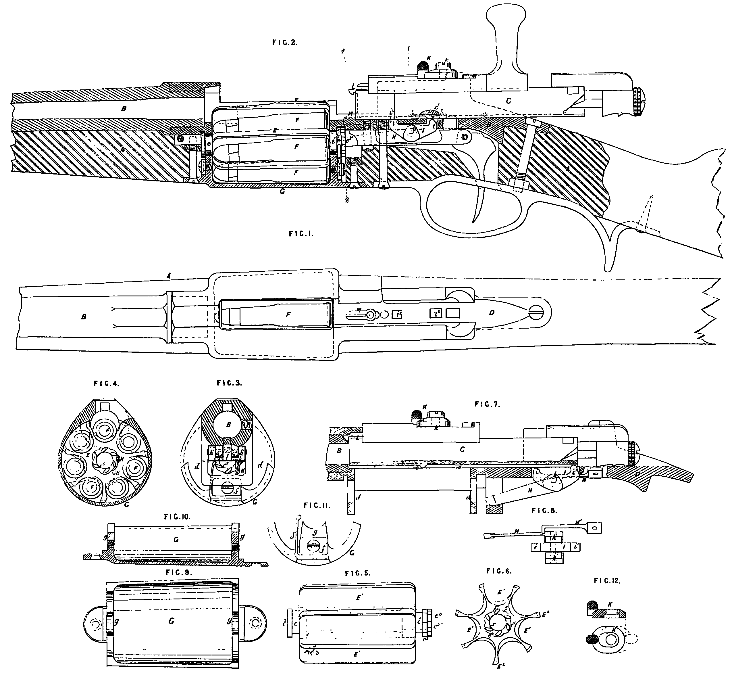
Figure 1 is atop view, and Figure 2 a central longitudinal section of a sliding bolt gun provided with the repeating mechanism of this Invention, the sliding bolt being omitted in Figure 1, and represented drawn back to open the breech in Figure 2.
Figure 3 is a cross section of the gun on line 1, —1, Figure 2; and Figure 4 is a similar section on line 2, —2, Figure 2.
Figure 5 is a side view, and Figure 6 an end view, of the revolving cartridge carrier or magazine, shown separately.
Figure 7 is a side view of the mechanism for rotating the said carrier or magazine; and Figure 8 is a top view of the lever forming part thereof.
Figure 9 is an inside view; Figure 10, a longitudinal section; and Figure 11, an end view of the removable cover enclosing the underside of the cartridge carrier or magazine.
A is the stock; 3, the barrel; C, the sliding bolt; and D, the shoe in which it slides; K is the revolving cartridge carrier or magazine located directly in rear of the breech, and parallel with the barrel, as shown. It consists of a sort of cylinder having a number of half round longitudinal grooves or chambers E¹ around it to receive the cartridges, which are separated by the radial wings E². The chambers E¹ correspond in cross section with the groove of the bolt shoe D, and in length with the cartridges F, which lie in them, as shown. e, e¹, are journals on the ends of the said carrier or magazine E, which arc mounted in bearings beneath shoe D formed by downwards projections d on the under side thereof, and by the ends g of the underside cover G; e²; e³, are shoulders on said journals to prevent any longitudinal movement of the cartridge carrier E. The latter rises through an opening cut in the under side of the shoe D, so as to bring the uppermost chamber E¹ into line with the groove of the said shoe D, with which it coincides, and thus virtually forms a continuation or part thereof for the time being.
The shoulder e³ of the rear journal of the cartridge carrier or magazine has as many notches e⁴ in its circumference as there are chambers E¹ in the magazine, and a nib on the end of a spring falls into one of said notches after each movement of the cartridge magazine E to arrest and retain it in the proper position. This spring is of the bent form shown in Figure 11,and is secured by a block f¹ fixed by a screw to the end g of the cover G. Upon the end of the journal e³ there are also formed a circle of teeth or projections c⁵ of the peculiar form shown, and corresponding in number with the number of chambers E¹. H is a lever arm working on pivots h mounted in ears h¹ on the under side of the shoe D. This lever is pressed upon by a spring H¹, and its free end acts on the teeth e⁵. This lever is made of steel, and is flexible laterally, so that after acting on one tooth and partially rotating the magazine, it can yield and spring past the outside of the next following tooth to take up its former position again. This movement of the end of tbc lever is illustrated in Figure 4. I is a sort of anchor piece formed of a pair of short arms in one with said lever extending on opposite sides of the axis h, and terminating in lugs i, i¹, whish rise through slots i² in the bottom of the shoe D.
c is a longitudinal groove on the under side of the sliding bolt C, into whish the lugs i, i¹, project, said groove extending from the front end backwards for a sufficient distance to allow the bolt to slide to and fro to the required extent, and terminating at the rear end in a short return groove at right angles to the longitudinal groove to allow the bolt to be partially rotated in order to lock the breech as usual. c¹ is a nib or projection at a certain point in said groove, which when the bolt is drawn back to its full extent strikes the lug i¹ (the lever H being then in the position shown in Figure 7) and moves the lever to the position Figure 2, thereby rotating the magazine to the extent of one tooth e⁵, as above described. On the return movement the nib c’ strikes and passes over the lug land depresses it, returning the lover H to its former position, Figure 7, in readiness to act on the next tooth e⁵’. Thus each time the bolt is drawn back, the magazine is partly rotated to bring another chamber E¹ containing a fresh cartridge in line with the barrel.
K, Figure 12, is an eccentric disc working on a pivot k; on the top of the bolt, and forming a stop which shuts against the upper portion of the shoe to limit the motion of the bolt. When placed in the position, Figure 2, the bolt can be drawn back to its full extent for operating the magazine, as above described, but when the stop turned in the position shown dotted in Figure 12, the bolt cannot be drawn back far enough for the nib c¹ to strike the lug i¹. The repeating mechanism is thus rendered inoperative, the gun being then loaded by hand in the ordinary way. L is the extractor, and M, the ejector for withdrawing and expelling the spent cartridge case when the bolt is drawn back,this being effected before the cartridge carrier or magazine is rotated, the latter movement not taking place until the sliding bolt attains its extreme backward position.
Having described the nature of the said Invention and the manner of performing the same, I declare that what I claim as the Invention to be protected by the herein-before in part recited Letters Patent is,—
1st. The combination with a sliding bolt gun of a revolving cartridge carrier or magazine constructed, applied, and operated by the backward movement of the sliding bolt, substantially as herein shown and described.
2nd. In a sliding bolt gun provided with a revolving cartridge carrier or magazine, as herein specified, the combination with the sliding bolt and the said carrier or magazine of the mechanism for rotating the latter, constructed and operating substantially as herein shown and described.
In witness whereof, I, the said Alexander Melville Clark, have hereunto set my hand and seal, this Thirtieth day of September, in the year of our Lord One thousand eight hundred and seventy-eight.
A. M. CLARK. (L.S)