
Britain 1561
A.D. 1878, 18th April. № 1561.
Magazines and Chargers for Fire-arms.
LETTERS PATENT to Benjamin Joseph Bernard Mills, of the Firm of Harris and Mills, of 23, Southampton Buildings, in the County of Middlesex, Patent Agent, for tile invention of “Improvement In Magazines And Magazine Chargers, or in Means or Apparatus for Loading Fire-Arms.” A. communication from abroad by Rollin White and Albert Henry Wheeler, of Lowell, in the County of Middlesex, and State of Massachusetts, in the United States of America.
Sealed the 28th June 1878, and dated the 18th April 1878.
COMPLETE SPECIFICATION filed by the said Benjamin Joseph Barnard Mills at the Office of the Commissioners of Patents on the 18th April 1878.
Benjamin Joseph Barnard Mills, of the Firm of Harris and Mills, of 23, Southampton Buildings, in the County of Middlesex, Patent, Agent. Improvement In Magazines And Magazine Chargers, or in Means or Apparatus for Loading Fire-Arms.” A communication from abroad by Rollin White and Albert Henry Wheeler, of Lowell, in the County of Middlesex, and State of Massachusetts, in the United States of America.
In the use of fire-arms for military purposes by cavalry, where the time for effective use of the same is usually very short, and where for that, reason revolvers appear to be preferred, it has been found very difficult to recharge the cylinders after they have been emptied by discharges on account of the necessity of employing one of the hands in guiding and managing the horse, on account of the irregular movements or motions of the animal, and frequently on account of the numbness of the fingers in cold weather. For these reasons, as well as on account of the mental excitement in actual conflict, it usually happens that in a charge of cavalry the chambers of the revolvers are discharged but once, and then reliance is had upon the sabre, or else the horsemen fall back and come to a halt for the purpose of recharging, The object in view then is to provide a magazine especially suited for revolving fire-arms, adapted to be secured to the body of the horseman, capable of holding in a secure manner protected from exposure to injury a large number of charges of ammunition, and having contrivances by means of which all the chambers of a revolver may be ‘charged instantly under all circumstances and in any sort, of weather.
The novelty in this Invention consists principally in a magazine adapted to be carried on the body, and capable of charging all the chambers of a revolver at the same time, and in the novelty of the various essential parts and in their various operative combinations all as will be more fully herein-after described and explained.
Also in a magazine adapted to be carried upon the person capable of containing a large number of cartridges, and provided with means for charging with a spring action at the same instant such of the chambers of a fire-arm as may be empty, instead of charging all the chambers at the same time as in the former description referred to; also having a pistol holster attached to the magazine in such a way that the cylinder thereof may be charged without withdrawing the pistol from the holster, and also in providing a suitable charger for such magazine.
And in order that the said Invention rosy be clearly understood and readily carried into effect; I will proceed to describe the same, having reference to the
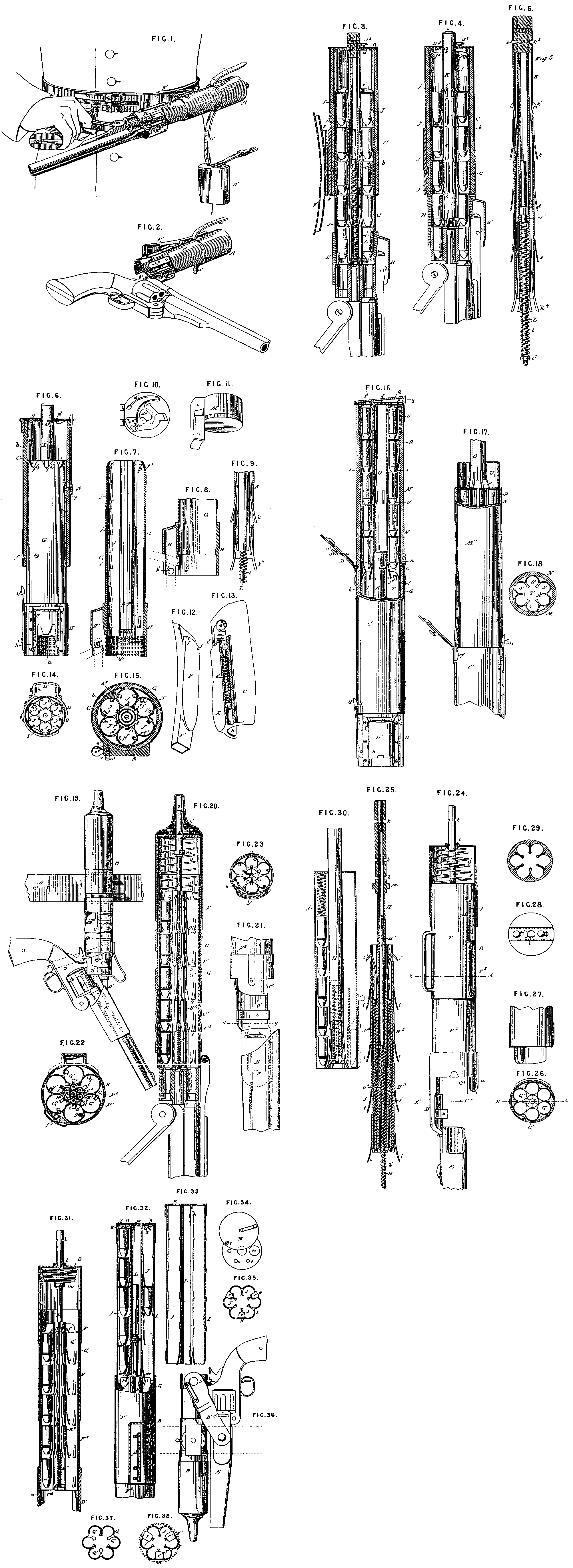
Figure 1 is a view of the magazine attached to the body of the wearer, showing the mode of charging the cylinder of a revolver.
Figure 2, a view of the magazine, showing the position of the revolver after the cylinder has been charged, and the pistol has been closed up for use.
Figure 3, a central vertical section of the magazine, with the cylinder of the revolver within the open end of the magazine before the act of charging the cylinder.
Figure 4, a similar section, after the cylinder of the revolver has been charged.
Figure 5, a similar section of the plunger and its various operative attachments.
Figure 6, a view of the magazine showing the inner shell in elevation, the outer shell in vertical section, and the charging guide in elevation, except that portion of it which receives the projection of the barrel, which portion is in section.
Figure 7, a vertical central section of the inner shell and the charging guide.
Figure 8, a modification of Figure 7.
Figure 9, a modification of Figure 5.
Figure 10, an inside view of the cap or cover to the magazine.
Figure 11, a view of the plug to close the open end of the magazine.
Figure 12, c, view of the swivel plate to which the bell, is attached.
Figure 13 a view of the swivel plate attached to the magazine, with a part broken away to show the enclosed spring.
Figure 14, a bottom end view of the magazine.
Figure 15, a central cross section of the magazine.
Figure 10, a vertical central section of the charger. inserted in the end of the magazine.
Figure 17, a modification of Figure 16.
Figure 13, a cross section of the charger.
Figure 10 is a side view of the magazine and the holster attached to a belt, with a revolver in the holster, in position assumed just before charging the cylinder from the magazine.
Figure 20, a vertical central longitudinal section of the magazine, the cylinder, the holster, and a, portion of the barrel of the pistol.
Figure 21, an enlarged view of the bottom of the magazine and the top of the holster.
Figure 22, a cross section on the line x, x of Figure 24.
Figure 23, a similar section on the line y, y, of Figure 21, looking upward.
Figure 24, a front view of the magazine and holster with the upper covering case removed, and the top in section.
Figure 25, a vertical central longitudinal section of the plunger.
Figure 26, a cross section near the. mouth of the magazine on the line x¹, x¹, of Figure 24.
Figure 27, a section on the line x, x, of Figure 26.
Figure 28, a top view of the magazine proper.
Figure 29, a cross section, being a modification in construction of the ammunition case.
Figure 30, a modification of the ammunition case, showing separate impelling springs in each chamber.
Figure 31, a vertical section of the magazine with the main driving spring arranged to force out the charges, and showing one chamber unloaded.
Figure 32, a vertical section of the charger in position upon the magazine.
Figure 33, a modification of the construction shown in Figure 32.
Figure 34, a view of the upper end of the charger, shown in Figure 32.
Figure 35, a top view of the charger.
Figure 36, a modification of the manner of securing the pistol to the magazine.
Figure 37, a view from above of the top of the ammunition case of the magazine.
Figure 38, a bottom view of the charger.
The description which follows relates to the magazine and charger illustrated in Figures 1, 2, 3, 4, 5, 6, 7, 8, 9, 10, 11, 12, 13, 14, 15, 16, 17, and 18of the Drawings annexed.
Like letters denote corresponding parts.
In the Drawings A and A¹ represent the leather, cases, which cover the opposite ends of the magazine; to a short strap secured to one of the leather cases, and a¹ another strap secured to the same leather case, with its buckle end passing over the outer end of the other case through a suitable guide, so that the end of the strap a may pass through such buckle, and the two cases A, A¹, be drawn towards each other, and held at the desired distance apart. The opposite end of the strap a¹ is secured to the belt B, so that the cases and the magazine enclosed in them may hang, if desired, at a convenient distance below the belt. This belt B is made in any convenient way and adapted to be worn around the waist, but it is apparent that any shoulder belt or other convenient means of support may be used, or the magazine may be attached to the body of the wearer in any convenient way, or the magazine with or without leather cases may’ be carried in a holster, or in some sort of cartridge box, or in a knapsack or haversack, it being only desirable that it should be at instant command for use.
As shown in the Drawings, and as the preferable mode, the magazine is secured directly to the belt.
The magazine is composed of several distinct parts which will be described in order, it being observed that the peculiar magazine, as illustrated in the Drawings, is designed for use with a revolver of the Smith and Wesson type.
The outer shell C is a cylinder made of any proper material, preferably of sheet metal, which has preferably a packing lining b of leather or other suitable material, or indeed the packing may be used without any shell. To the top of this shell C is hinged a cap or cover D, which, when closed, is held fast by a spring latch c. Upon the inside of this cap or cover, shown particularly in Figure 10, is a hook d actuated by a spring d¹, which hook is adapted to engage with a slot or score in the plunger, herein-after to be described, and to hold the same in position. This spring d¹ is shown with its free end inserted in holes d⁴, where it operates the hook as described; but the free end may be inserted in the other holes d⁵, in which case the hook is held constantly back out of position of engagement. This plunger passes through a proper opening d² in the cap or cover. The hook d is actuated from the outside of the cap or cover by a proper stud d³.
Upon the outside of the shell C is secured a swivel plate E, having a suitable pivot, which plate has a hollow space under it for the reception of a lock e, which lock has a spiral spring e¹. Upon the head of this lock is a hook e², adapted to engage in the periphery of the swivel plate E of the belt, so as to hold the magazine at any convenient angle, and this lock is operated by means of a suitable stud e³.
The swivel plate E is pivotted upon the swivel plate Fin any convenient method, and its periphery is notched as at f for engagement with the hook e². This plate F is secured to a convenient eliding clasp F¹, through which the belt B may be threaded, or the belt may be threaded through a loop attached to the magazine. Upon this shell C there is a suitable notch f¹ for engagement with a spring latch, herein after to be mentioned. In the same shell also is inserted a proper screw pin f², which extends into its interior, and passing into a slot g, upon the inner shell G¹, limits its movement back and forth to the extent of the length of such slot. This inner shell is scalloped at its top, as shown by f³. The inner shell G is made of proper material, preferably thin sheet metal, and is designed to fit closely into the interior of the shell C; it may be made cylindrical or polygonal, in whole or in part, and has on one side of it a slot g, into which the pin f² enters, as explained above, and limits its movement back and forth, and prevents its rotary movement. Upon the outer end of this shell is secured the charging guide H, made of a size and form to receive into its interior the cylinder of the revolver to be charged, and it has upon one of its sides a portion H¹, made of a size and form to admit of the reception within it of the projection of the barrel of the pistol, or that part which locks the pistol barrel to the recoil shield. This guide H, H¹, may be made a little flaring at its mouth for more convenient use. Upon the side of this portion H¹ is a spring latch h¹, which engages in any suitable way with the projection of the barrel; when the pistol is so far withdrawn after charging as to withdraw the cylinder from the magazine, and holds the pistol until it is turned into proper position for locking. The interior of the guide H may be roughened, as shown at h, so that if dirt or dust should find its way in, it would not obstruct the entrance of the cylinder. Upon one of the sides of this shell G is a spring detent h⁴, the office of which is to fit into the longitudinal slot or recess for the locking bolt which is found in the cylinders as constructed, and serves to hold the chambers of the magazine. Upon the same shell G is a spring latch h², which engages with the notch f¹, upon the shell C, and holds the two shells together. Within the shell G, and secured to it by suitable means h³ is fitted the ammunition case I, made preferably of thin sheet metal, and composed in this instance of six tubes J, J, J, arranged around a central plunger, and secured together, but the whole case may be made of solid metal like a cylinder, and properly bored out. In these chambers J, J, are inserted springs j, j, extending into the interior of such chambers with their free ends pointing towards the loading end of the magazine, and of these springs five are shown in the Drawing; the ends of such springs being apart the full length of a cartridge. Instead of a spring, for economy of space, a spring hook j¹ is placed at the upper end or the end opposite the loading end of each of the chambers J, J; these springs j,j, and hooks j¹, j¹, serve to hold the cartridges from moving backward in their progress toward the loading end, and also to prevent their dropping out. It is evident, that instead of such springs, pawls, or tooth bars, or other equivalent devices operating in the same way may be employed. In the interior of each chamber J, J, nearest toward the centre of the case I, are longitudinal slots j², j², in which traverse springs k, k, and hooks k¹, k¹, secured to the plunger K, similar to the springs j, j, and hooks j¹, j¹. Placed centrally within the case I, and centrally as to the chambers J, J, is the plunger K, which is a metallic tube, the top of which k² is solid for a short distance, in which part is cut a groove k³, with which the hook upon the cap engages. In the lower interior part of this plunger is secured a rod L, having around it a suitable spiral spring l, which extends from a shoulder l¹ in the tube to a nut l² or shoulder on the bottom of the rod into which the rod is screwed. The lower series k of these springs are secured within the interior of the plunger and bent outwardly below its lower end, at which point they are thicker and stronger. When these springs strike upon the base of the cartridges to drive them home into the cylinder, they ride upon the nut or shoulder on the bottom of the rod L, and efFectually prevent the next series of cartridges from dropping down until the plunger is withdrawn to charge again.
The top of the ammunition case I is scalloped as at i to correspond with the scalloped portion f of the inner shell G for the purpose of facilitating the pressing the cartridges into the chambers J, J, more conveniently when filling such chambers by hand.
The construction of the magazine is complete with the addition of the plug M, made of any suitable material, and adapted to fit closely into the interior of the charging guide H, H¹, in which it is held by friction, and by the pressure of the springs connected with such charging guide H, H¹, or it may be locked in place by one or more of such springs; this plug not only excludes dust and moisture but it assists in holding the cartridges from falling out.
The manner of operation of the various parts of the magazine, and of the entire magazine is as follows:— It being premised that the magazine is supposed to have been filled by hand with cartridges thrust in from the top, one by one, until each of the ammunition chambers is full, as shown in Figures 3 and 4, and it being also supposed that s horseman is carrying the magazine attached to his belt, as shown in Figure 1. The magazine being turned into a convenient position upon its swivel, the meeting faces of the plates of whish may be packed with any suitable material to prevent the intrusion of dust and water, and to better retain any lubricant, and the plug being removed the magazine is now ready for charging the revolver.
The horseman holds his revolver, which is supposed to be unloaded, with his right hand with the usual grasp for firing, breaks it down with the same hand, thus exposing the end of the cylinder in the usual way for loading, disengages the spring latch h², when the inner. shell slides out by the action of the spiral spring in the plunger, and then thrusts the end of the cylinder and the projection of the barrel into the charging end of the magazine, as shown in Figure 1.
When the cylinder is locked, when thrown open, as in some instances, by a spring stop upon the projection, the chambers of the cylinder will be in line with the ammunition chambers of the magazine. In instances where the cylinder is not thus locked it will be necessary to revolve the cylinder until the spring catch or detent h⁴ gets into position, which will arrest the cylinder in line with the ammunition chambers.
The cylinder being inserted, as described, in the charging end of the magazine, is locked therein by means of the spring latch h¹, and force being then applied by the hand holding the pistol the cylinder is pushed back in turn, pushing the inner shell G into the outer shell, until the two shells are locked together by means of the spring catch h²; at the same instant the springs k, k, upon the plunger K force a cartridge from each chamber of the ammunition case into the corresponding chambers of the cylinder, as is shown in Figure 4. The cylinder is then withdrawn, and the projection of the barrel being held by the spring latch swings upon the same in the act of closing up the pistol, and at the same time as the line of direction of the barrel is changed in the act of closing up the projection is released and readily comes out of the charging end of the magazine.
If it is desired to charge the cylinder of the revolver by operating the plunger alone, which may be done as well with the leather case on as when it is removed, the plunger passing through the end of such leather case, as shown in Figure 1, it is necessary to release the end of the plunger from the hook d, upon the cap D, when the plunger will protrude a sufficient distance. In this case however the spring latch h² remains in position, holding the outer and inner shells together; then by pressing the cylinder inwardly, which has been entered into the charging end of the magazine, and allowing the end of the plunger to come in contact with the left arm, the cartridges will be forced down into the cylinder, as before described; or the end. of the plunger may be struck with the left arm or the left hand.
It will be perceived in the operation of this plunger that the hooks k¹ carry along the upper series of cartridges while the ends of the springs k, k, force down cauli of tile other series of cartridges at the same time that the springs j, j, prevent the cartridges from being moved out of place upwardly by any agitation or jolting of the magazine, while the springs k, k, bending inwardly under the fronts of the cartridges prevent their movement in the opposite direction.
It will be observed tint the lower series of the springs k⁴ of the plunger K are fastened to the interior of the plunger, and are stouter than the other springs k, and serve better their purpose of driving the cartridges home in the chambers of the cylinder, and they also prevent the next series of cartridges from coming out.
In the modification shown in Figure 8, it will be observed that instead of the spring detent h¹, shown in Figure 7, there is a stud in the charging end adopted to engage with a corresponding stud or equivalent in the projection.
It will also be observed that in Figure 9 is shown a modification of the springs k, k⁴, by the use of pawls.
It is to be observed that while I have described particularly the mode of construction, I do not intend to be restricted in such details, as in the actual construction of the magazine for use it, will be deemed advisable to’ simplify details to the largest extent. It is apparent that the magazine may be charged by hand by inserting the cartridges one by one into the ammunition chambers, but it is believed that it will be vastly more convenient to use the charger M, which I now proceed to describe, and which is intended to be carried in the knapsack or in any convenient way about the person or the saddle of the soldier.
The shell N of this charger is made of any suitable material, preferably of sheet metal of any convenient length, that shown in the Drawing being made to correspond with the magazine heretofore explained, and having a capacity for thirty cartridges, and of a size to correspond with the shell of the magazine which is to be charged. The bottom of this shell is scalloped or serrated to correspond with the scalloped portion fs of the inner shell G and i of the ammunition case I, all of which scallops are so arranged that when the shell N of the charger is inserted into the interior of the inner shell G, the scalloped portions of the charger interlocking with those of the inner shell will bring the ammunition chambers of the magazine and those of the charger in exact line. These scalloped portions not only serve as guides automatically but regulate the distance of penetration of the charger, and prevent its revolution out of the proper line of direction of the ammunition chambers. Upon the outside of this shell, near its lower end, is a stop or notch n with which the spring latch c engages and holds the charger firmly in position, and there may be necessary an additional spring latch n¹, opposite the latch c. Upon the inside support part of the shell are spring hooks n², n³, adapted to catch over the tops of the cartridges in each of the ammunition chambers of the charger, and hold. them down in place and prevent their being moved upwardly. In the centre of this charger is a plunger O, to which is secured a cap P, which serves as a cover to the charger, and projecting a little on all sides beyond the sides of the charger, serves to give a firm grasp for withdrawing the plunger. In this cap are openings p, p, corresponding with and in line with the chambers of the ammunition case
Upon the outsides of the.plunger are springs o, one or more for each of the ammunition chambers, with their free ends the distance apart of the length of a cartridge, and bent inwardly so as to engage with the outer rim of the cartridge.
Hinged to the top of the cap P is another cap Q, whose office is to close the openings p, p, and exclude dirt or dust, and this cap Q has a spring latch q adapted to fit and fasten one of the rims of the cap P.
Enclosed within the shell N is the ammunition case R, made of any proper material, preferably of thin sheet metal, having in this instance six chambers S arranged around a central longitudinal opening T, in which the plunger plays. These chambers are of the proper size for the cartridges designed to be held in them, and instead of being made with the case or separately the case and chambers may be made of solid metal or any proper material bored out. Spring latches s, s, one or more for each chamber, have their free ends projecting into such chambers at such distances as to rest upon the top of a cartridge and hold the same down in place.
It being obvious that for some purposes it is desirable to limit the withdrawal of the plunger, a modification of the charger is shown in Figure 17, where the plunger O passes through a shell U, which when the plunger is forced down, is forced down its depth, between the shell N and the ammunition case R, and when the plunger is withdrawn its lower end is retained at about the bottom of the shell U by means of a spline u to limit the motion of the cap and plunger upward.
The manner of operation of the charger is as follows:— The hinged cap Q being raised, when the cartridges may bc inserted by hand and pushed down one upon the other until the ammunition chambers are filled, the hinged cap is then closed, and fastens itself securely by its spring latch g, The charger being now filled, in order from it to charge the magazine, the cap Q of the latter being raised, as shown in Figure 10, tbc lower end of the charger is inserted in the upper end of the magazine, and the plunger of the charger being withdrawn more or less, as may be required, so that the ends of the springs o, o, shall engage over the bases of any series of cartridges; the plunger is forced down by hand, thus forcing the cartridges out of the ammunition chambers of the charger into the corresponding chambers of the magazine, the charger and the magazine being held together during this operation by means of the spring c, or the springs c, n¹.
In the modification shown in Figure 17 the mode of operation is the same, the outward movement of the plunger of the charger being limited, as before described.
In the foregoing descriptions of the mode of use both of the magazine and of the charger, it will be observed that they are made as applicable to a horseman, but it is evident that both the magazine and the charger may be used by a man on foot who has complete freedom for both of his hands in any convenient way. It will be noticed also that the charger may without material change of construction be used directly for charging the cylinder of a revolver. Also that instead of the charger extra ammunition cases may be used, which may be inserted directly into the magazine, the unloaded ammunition case being removed; also that many modifications of size, form, and use, both of the magazine and of the charger may suggest themselves after experience, all within the scope of the Invention.
The description which now follows relates to the magazine and charger illustrated in Figures 19 to 38 inclusive of the accompanying Drawings,—
A denotes the belt, to which the magazine 8 is attached by a swivel connection, as shown in Figure 19, in such a way that for convenience in carrying, the magazine may present itself in a horizontal position, or nearly so, and when used in the act of charging the pistol, in a vertical position, or nearly so.
The magazine, however, may be threaded upon the belt through a loop, as shown in Figure 24. A cap or cover C of any suitable material protects the upper or inlet part of the magazine from the evil effects of exposure, whilst another cover C¹ preferably of suitable flexible material covers the greater portion of the lower part or outlet of the magazine, and to this part is secured a mouth C², preferably of sheet metal. A latch a serves to bold the chamber of this cylinder in the proper line for charging, and a suitable plug D is held in place by a spring b. An extension D’ of one side of this mouth serves as the means of connection between the magazine and the holster Fe but instead of this extension there may be a separate strap or link of metal, or of any suitable material, and this strap may be rigidly secured to the magazine or its mouth, or may be secured to either with any sort of pivot or swivel. The end of this extension, strap or link D¹, however, which is attached to the holster should preferably haves pivotal connection for convenient operation, one form of which is shown at c in Figure 21; and for convenience should also have means for holding the holster at difFerent angles of inclination, as is shown at d in the same Figure, which may be a set screw working in a curved slot e, or any other usual contrivance.
Upon this extension D¹, as shown in Figures 21 and 23, a spring b whose, free point passing over the outside of the cylinder when it is revolved by hand, after it has been inserted into the mouth of the magazine, will engage in one of the longitudinal slots f¹ of the cylinder, shown in dotted lines in Figures 19 and 36, as extending the whole length, hold it with its chambers in line with the ammunition chambers of the magazine.
In Figures 26 and 27 is shown a tapering projection f⁴ within the mouth C² of the magazine, of a size and form corresponding with the grooves f¹ of the cylinder, and the office of this projection is to enter the grooves f¹ of the cylinder, as it is moved up into the mouth C², and thus guide its chambers into line with the ammunition chambers of the magazine, and hold the cylinder in proper position.
The holster E, made of any suitable material; and preferably only long enough to give a proper support to the pistol, is suspended attached to the magazine or its mouth as described. When the pistol is in the holster, as shown in Figure 19, it may be secured by any proper strap or elastic band g.
The magazine proper is composed of an outer shell or case F made of any suitable material, preferably sheet metal, in two portions, one of which covers the upper or inlet portion of the ammunition case, and also the upper portion of the other part of the outer shell F¹, over which it has a telescopic movement, and both parts F and F¹ have a telescopic movement over the inner shell, to which the flexible character of the cover C¹ offers no impediment.
To limit this movement of the part F over the part F¹ there is a slot f upon the outer shell, with a locking notch or notches, in which slot a proper screw or pin f⁴ secured to the outer shell F¹ traverses back and forth, and in like manner the movement of these outer shells over the inner shell is limited by suitable contrivances f³. The inner shell F², which is made of may suitable materiel, is secured to or preferably within the mouth C², and may serve as a case for the ammunition chambers, or these chambers above may be used in lieu of the shell F². Upon this shell, as described, or upon the ammunition case proper, if used as a substitute, the outer shell F, F¹, when the two parts are united together has a, telescopic movement restrained as before described.
Enclosed within the magazine proper F, F¹, is the ammunition case G, made of suitable material, and composed of any desirable number of tubes or chambers G¹ arranged around a common centre, six in number, in the one shown in the Drawings, and of a capacity each to hold five cartridges. From the inner walls of these chamber springs g¹ point downwardly with their free ends projecting inwardly, and are arranged apart about the distance of the length of a cartridge, which springs serve to keep the cartridges from upward movement in the chambers, end also to hold the cartridges from dropping out or dropping down out of position. It is evident, however, that there ere many known varieties of spring detents which would operate in the same way as the springs g, and are therefore proper equivalents for the same.
The plunger is situated centrally as to the ammunition chambers, and is composed of a tube H having a rod H¹ to move up and down in its interior, the lower part of the rod having a spiral spring k around it. About this tube and rod are tubes H², H², as many in number as the number of ammunition chambers G¹, which tubes have attached to them springs i, i, pointing downward and outward, as many in number as there are cartridges contained in each ammunition chamber G¹ when it is full, and having their points apart the length of a cartridge, which points serve to force down the cartridges against the bases of which they strike.
Hooks i¹, i¹,serve to hold the upper series of cartridges from moving upwardly. In each of these tubes H’, H, are rods H, H, having spiral springs j, j, around them, and these tubes close in at the bottom and embrace the lower ends of such spiral springs. In the tube H are recesses k, k, in which a sliding catch l on the top of the outer shell operates to lock said tubes in the desired position as it passes through said top. Upon the tube is a disc shoulder m, upon which the bottom of the mainspring O rests, as shown in Figure 31
If now the tube H being locked in the, position shown. in Figure 31 is released from the catch l, the plunger will be thrown down with great force, its springs i, i, engaging with the bases of the cartridges, and forcing the cartridges contained in the ammunition chambers into the chambers of the cylinder to be charged. If, however, any chamber of the cylinder is already charged, the cartridge in the ammunition chamber next above the cartridge in the cylinder wLLL rest against such last-named cartridge, and the tube H² is forced upwardly the length of a cartridge, and when the plunger is withdrawn the springs j, j, will return the tubes to position. In brief, these tubes are so arranged to operate with a yielding pressure, that their springs force down a cartridge where there is a vacancy to receive it, but when there is no vacancy for the cartridge then the tube H² yields to the pressure and ceases to force down the cartridge, and thus this plunger will charge only empty chambers in a cylinder, and will always charge all the empty chambers in such cylinder.
A modification of the ammunition case, which may also serve as a charger, is shown in Figure 30, wherein the springs i¹, i¹, on the plunger are all dispensed with, except the lower series designed to force down the lowest series of cartridges into the chambers of the cylinder, and the rods H³, H³, and springs j, j, are dispensed with, but instead, a spiral spring j¹ is inserted above all the cartridges, which presses them down into proper position, but if every chamber in the cylinder is already charged, then the spring j yields to the upward pressure.
In this ammunition case or charger an opening covered with a slide is shown in dotted lines in Figure 30, as also a plunger rod and spring to return the plunger to position after forcing down a cartridge by hand. The withdrawal of the rod is less than the length of a cartridge.
In the modification of the ammunition case shown in section in Figure 29 the outer spaces between the shells are shown as filled up with any proper material, or else that the entire case should be made solid out of some proper material and then bored out.
In this modification of the ammunition case illustrated in Figure 20 are shown separate ammunition tubes, which may be made of hard rubber, gutta percha, or equivalent material, and steel or other proper metal strips separating the tubes with recesses in them to receive guides attached to the charger, and these tubes may have a metal or gutta percha or other proper shell around them.
The method of operation of the magazine is as follows, supposing the chambers of the pistol to be unloaded or partially unloaded:— The tube of the plunger is withdrawn and set in position, as shown in Figure 31, with the mainspring 0 compressed between the disc on the tube of the plunger and the inside of the top of the magazine, the tube itself being retained in position by the spring catch in the top of the magazine. The pistol is then inserted into the holster, as shown in Figure 19; it is opened or broken down by a hand, which grasps the pistol, and by a forward movement of the same band the cylinder of the pistol will be pressed into the mouth of the magazine, the cylinder itself being revolved by the spring 5, so that its chambers will be on line with the chambers of the ammunition case. In this position of the cylinder it will be held by any suitable spring catch, as shown in Figures 24 and 26. The hand then being raised to the top of the magazine, the spring catch which holds the tube, of the plunger is released, the plunger under the impulse of the mainspring flies down, and the lower series of cartridges are forced by the springs of the plunger into the proper chambers; the plunger to be withdrawn and fastened as before described before the cylinder is removed from the plunger.
For convenience of operation some well-known attachment may be made to the spring catch which holds the tube, so that the same may be operated by the hand in any position along the magazine, or even as it grasps the handle of the pistol.
As before explained in the operation of the plunger only those chambers of the cylinder which are empty will be charged when the plunger flies down under the impulse of its mainspring.
Should it however be deemed more convenient under any circumstances to operate the plunger directly by manual force the mainspring O is reversed, as shown in Figure 24, where the body of the spring passes entirely over the disc m, on the plunger tube and rests upon the top of the ammunition case. In this instance the plunger is operated by manual force, as explained in an earlier portion of the present description, and the mainspring serves only to return the plunger to its normal position.
After the cylinders are charged as described, a backward movement of the hand withdraws the cylinder ‘from the mouth of the magazine, a forward movement closes np the pistol, and it is ready to be withdrawn for use.
If it is desired to carry the pistol continually in the holster described, the magazine may be secured vertically, as shown in Figure 19. and the pistol be carried in the holster below it, for convenience, being secured to the magazine by a proper strap or equivalent fastening; or the magazine may be secured upon the belt in a horizontal or nearly horizontal position, and the holster thus bc brought up to the belt or near it, to which it may, if need be, be secured in any convenient way; or the magazine may be reversed, as shown in Figure 30, and the holster, which in this instance is attached to the magazine by a connection having a pivot at each end, will be arranged by the side of the magazine, and the pistol will be carried by the side of tile magazine and close to it, and in this position may be secured firmly by any proper strap or equivalent means. In charging this magazine it is proper to remove the upper portion of the outer shell, when the cartridges may be inserted by band in the separate ammunition tubes until the same are filled.
It is evident however that this filling can be done more expeditiously by a charger, which I proceed to describe, and which as a whole is designated by the letter I. This charger is composed of an ammunition case having a number of ammunition tubes J, in this instance six, arranged about a common centre. A top cap K covers the top of the ammunition case, and another cap covers the bottom of the same case. This top cap K has attached to its centre the plunger L, which for convenience is a tube, and has also in it one or more openings n coinciding with the mouths of the ammunition tubes; or if the top of the cap has a rotary freedom thon one of such openings is sufficient. The object of this opening n is to allow the insertion of the cartridges into the ammunition tubes in the act of filling them. If but one such opening n is used there are other smaller openings o, o, in the top of the cap, each opening being in line with the interior of one of the ammunition tubes, the office of which small openings o, o, is to permit the insertion of a proper rod to force down the cartridges if necessary, which rod when not in use is attached in some convenient way to the ammunition case. Upon the top of this cap is, pivotted a cover M, the pivot 2 of which may be a rod passing down between the outsides of two of the ammunition tubes through proper guides, and thus serving as a guide to keep the plunger always in the proper position, Fastened upon the ammunition case at the top are springs N, with their free upper ends r turned inwardly, which springs for convenience are three in number, and arranged so that each free end will cover a portion of the top of two contiguous ammunition tubes. These springs, when cartridges are forced in, will yield sideways, and allow the cartridges to be inserted, but when the cartridges are in, the ammunition tubes will prevent their movement upwardly.
The lower cap has nothing peculiar about its construction, but it may have openings in it, by means of which a rod may be inserted to force the cartridges upwardly if need be.
Upon the lower part of the ammunition case are arranged other springs N¹, whose free lower ends r’ bend inwardly, and which are arranged in reference to contiguous tubes like the springs N, and thus may be held more securely’ inwardly so as to prevent the cartridges from dropping out by a ring N², shown in dotted lines in Figure 38; or instead of the ring a cap or other suitable device may be used. The office of these springs is to prevent the cartridges from dropping out of the ammunition tubes.
The ammunition tubes J are secured together in any convenient way, and are slotted in that portion nearest to the common centre.
The plunger L has freedom of movement up and down in the centre of the ammunition case, and is restrained from coming entirely out by any proper stop, and the plunger has near its bottom suitable springs s, s, with free ends pointing downwards, one of which springs extends into the interior of each of the ammunition tubes through the slot before mentioned.
These springs afford no resistance to the downward passage of cartridges when the charger is being filled, and when the charger is withdrawn and forced down these springs striking against the bases of the cartridges force them down and out of the ammunition tubes.
If it is desired to fill this charger from the lower end the springs N¹ are withdrawn outwardly by hand, when the openings of the ammunition tubes will be uncovered. The cartridges being inserted with the bases forward the bases will strike against the free end of the springs s, s, which when the plunger is down protrude a little below the bottom of the plunger, and thus these springs will offer no obstacle to the admission of a cartridge.
In Figure 33 is a modification of the charger shown in Figure 32, in which the upper and lower springs N and N¹ are omitted, und instead of them springs to hold the cartridges in position are inserted in each ammunition tube, and instead of springs on the plunger there are studs, projections, or ratches on the plunger, and a hook spring at tile top to keep the cartridges from coming out, or a ratchet bar clay extend the whole length of the plunger tube, and have play in and out of it, regulated by a spring.
Instead of a recess in the plunger tube this plunger may be solid, and the ratchet bar attached to it with freedom to play in and out oF the ammunition chamber.
In using this charger to charge the magazine the bottom oF the charger is inserted into or coupled to the top of the magazine, and the plunger of the charger being withdrawn and then forced down the contents of each of the ammunition tubes of the charger will be forced into the corresponding ammunition tubes of the magazine.
It is to be understood that I do not wish to confine the use of this charger to the loading of a magazine, for it may be readily applied directly to the charging of a cylinder of a pistol; neither do I wish to be confined to the various details of construction in either the magazine or the charger, because in practice it will be endeavored to simplify the construction of each to the fullest extent.
The advantages of the construction described will be evident upon inspection to those skilled in the business, and besides are related in the preceding description.
Having thus fully described the Invention, and explained the manner of using the same, I would have it understood that what I claim as new therein is, —
First. A magazine adapted to charge all the chambers of a fire-arm at the same time, substantially as described.
Second. A magazine capable of holding many charges of ammunition, and adapted to charge all the chambers of a revolver at the same time, substantially as described.
Third. A magazine adapted to charge all the chambers of a revolver at the same time and provided with suitable means for attachment to the person, substantially as described.
Fourth. A magazine adapted to be secured to the belt of a person with a swivel connection so as to bc capable of presentation at, any desired angle, substantially as described.
Fifth. A magazine adapted to receive and retain in place the cylinder of a revolver while the seine is loaded from the magazine, substantially as described.
Sixth. A magazine adapted to permit the cylinder of a revolver to be withdrawn after it is loaded from the magazine, while it holds the projection of the barrel in such s, way that the withdrawal of the cylinder will elute up the pistol, substantially as described.
Seventh. A magazine containing an ammunition case, provided with chambers corresponding to the chambers in the cylinder of a revolver or fire-arm, substantially as described.
Eighth. A magazine or ammunition case having a plunger, by means of which all the cartridges for one charge of a cylinder or fire-arm are ejected at one time, substantially as described.
Ninth. A magazine or ammunition case provided with mesne to eject one series of cartridges at a time, and to hold the remaining cartridges from movement in any direction, substantially as described.
Tenth. A magazine or ammunition case provided with means to hold its chambers in line with the chambers of the cylinder in the act of charging, substantially as described.
Eleventh. In connection with a magazine or ammunition case a charger capable of containing many charges of ammunition, substantially as described.
Twelvth. In connection [with a magazine or ammunition case a charger containing ammunition chambers corresponding with the ammunition chambers of the magazine or ammunition case, substantially as described.
Thirteenth. In connection with a magazine or ammunition vase a charger provided with means for loading all the ammunition chambers of the magazine at the same time, substantially as described.
Fourteenth. In combination with a magazine or ammunition case a charger adapted to load all the ammunition chambers of the magazine at the same time, and both magazine and charger having means to automatically present the chambers of both in the same line in the act of charging, substantially as described.
Fifteenth. A magazine or ammunition case and a charger for the same, constructed, arranged, end operating substantially as described.
All of the above elaine are based upon the construction shown in Figures 1, 2, 3, 4, 5, 0, 7, 8, 9, 10, 11, 12, 13, 14; lo, 10, 17, and 1S of the Drawings annexed.
Sixteenth. An independent magazine for charging a revolver, having attached to it a holster adapted to hold a pistol, substantially as set forth.
Seventeenth. An independent magazine for charging a revolver, having a holster attached to it in such a way that the cylinder of the pistol may be charged while the pistol is in the holster, substantially as set forth.
Eighteenth. An independent magazine for charging a revolver having a holster attached to it in such a way that the pistol while in the holster may be secured to the magazine for safe carriage, substantially as set forth.
Nineteenth, An independent magazine for charging a revoIver adapted to charge at the same time the chambers of the cylinder by a positive spring motion, substantially as set forth.
Twentieth. An independent magazine for charging a revolver adapted to charge all the empty chambers of the cylinder without disturbance of the charges already in such chambers, substantially as set forth.
Twenty-first. An independent magazine for charging a revolver having means by which the plunger may bc operated by spring pressure or by hand, as may be desired, substantially as set forth.
Twenty-second. A charger for a magazine for a revolver having a plunger attached to its cover or cap, substantially as set forth.
Twenty-third. A charger for a magazine for a revolver having springs between its contiguous ammunition tubes at the top and bottom, substantially as set forth.
Twenty-fourth. A charger for a magazine for a revolver or fire-aim having independent means for discharging the contents of its ammunition tubes separately, substantially as set forth.
Twenty-fifth. A charger for a magazine for a revolver having means for preventing the cartridges from falling out, substantially as set forth.
Twenty-sixth. In combination with a magazine adapted to load only the empty chambers of a cylinder a charger adapted to discharge the contents of its ammunition tubes separately, substantially as set forth.
Twenty-seven. In a magazine or charger placing the cartridges end to end for feeding, substantially as described.
In witness whereof, I, the said Benjamin Joseph Bernard Mills, have hereunto set my hand and seal, this Twelfth day of April, in the year of our Lord One thousand eight hundred and seventy-eight.
B. J. B. MILLS. (L. S.)